Analog to Digital Converter (ADC) in nRF52833
The nRF52833 features a 12-bit Successive Approximation Register (SAR) ADC, referred to by Nordic as the SAADC, and supports up to 8 input channels for analog measurements.
Here is a mapping of analog input channels (AIN0 to AIN7) to their corresponding GPIO pins on the nRF52833.
| Analog Input | GPIO Pin |
|---|---|
| AIN0 | P0.02 |
| AIN1 | P0.03 |
| AIN2 | P0.04 |
| AIN3 | P0.05 |
| AIN4 | P0.28 |
| AIN5 | P0.29 |
| AIN6 | P0.30 |
| AIN7 | P0.31 |
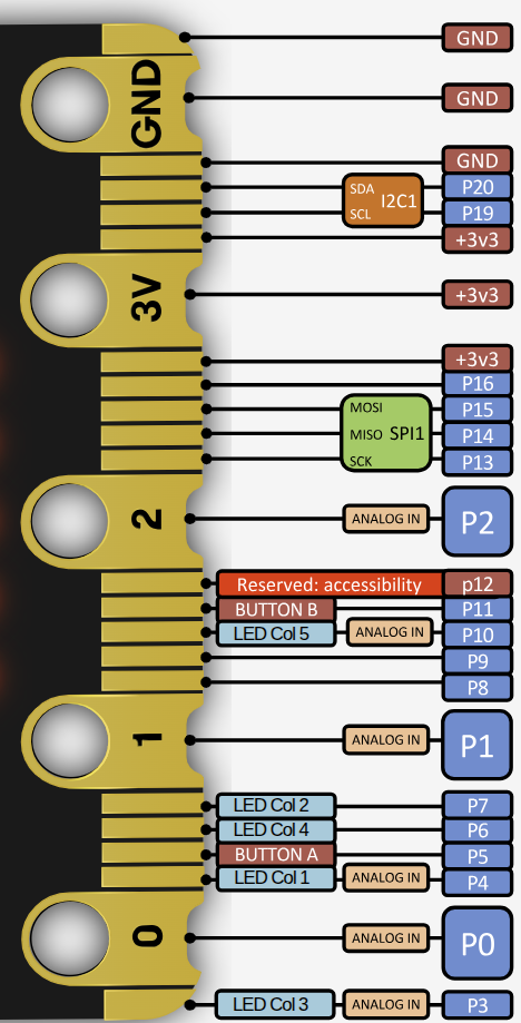
Microbit Pin Layout
This table shows which analog input channels on the nRF52833 are accessible from the micro:bit v2 edge connector. The large pins (Ring 0, Ring 1 and Ring2) provide safe and direct access to analog input without conflict. The small pins (3, 4, 10) are also ADC-capable but are shared with the LED matrix, so they should only be used for analog input when the display is disabled.
| microbit Pin | GPIO (nRF52833) | Analog Input | Accessible via | Shared With | Notes |
|---|---|---|---|---|---|
| 0 | P0.02 | AIN0 | Large ring | — | Fully available |
| 1 | P0.03 | AIN1 | Large ring | — | Fully available |
| 2 | P0.04 | AIN2 | Large ring | — | Fully available |
| 3 | P0.31 | AIN7 | Small pin 3 | LED Column 3 | Only usable when display is off |
| 4 | P0.28 | AIN4 | Small pin 4 | LED Column 1 | Only usable when display is off |
| 10 | P0.30 | AIN6 | Small pin 10 | LED Column 5 | Only usable when display is off |
