Intro - Embedded Rust Programming with Microbit
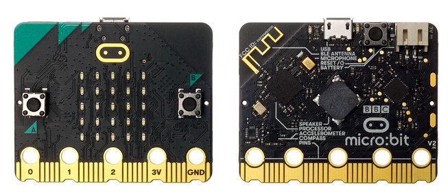
In this book, we use the Microbit (v2) with Rust to build simple and fun projects. The board is officially called "micro:bit". I will refer to it as both microbit and micro:bit interchangeably. The Microbit is widely used for learning purposes and comes with several built-in components, including an LED matrix, microphone, buttons, speaker, Bluetooth, and more.
Prerequisites
- Rust basics: You should have a basic understanding of Rust. This book doesn't cover the fundamentals of the language. If you're new to Rust, I recommend starting with the official Rust book. You can also find other resources here.
Meet the Hardware
You can search for "Micro Bit V2" on e-commerce websites and choose the option that suits your needs. You may buy just the board, or a package that includes accessories like a battery and micro USB cable. Some sellers also offer kits with additional sensors. It is up to you to decide which version fits your project best. You can refer the official microbit website also to find the seller.
Note: I purchased the Micro Bit V2.21 with the accessories(micro USB cable). You might receive a different V2 version, which is fine as long as it is a V2 variant (not the older V1). I also bought other sensors as I went along (but dont worry about that now).
Why this book?
There's already a nice book called "Discovery" that covers embedded Rust with the micro:bit. So you might be thinking - why write another book? Well, why not? :) Honestly, one of the best ways I learn and really dig into something is by teaching it to others. When I explain stuff to others, it helps me understand it better too. So this book is me learning out loud and bringing you along for the ride.
Like the other "impl Rust" books for the ESP32 and Raspberry Pi Pico, this one is meant to be fun and hands-on too. Hopefully someone out there finds it useful - that's the goal behind writing it.
Other Learning Resources
-
The Embedded Rust Book : This is a great resource if you're just getting into embedded Rust. You don't have to read it before jumping into this book, but it's a good place to start. I'll do my best to explain things as we go, but if I miss something or don't cover it clearly, this book can really come in handy. One way or another, I definitely recommend giving it a read.
-
Discovery: This is the book I mentioned earlier. It covers embedded Rust programming with the micro:bit. You can read it in any order - either start with "impl Rust for Microbit" and then read "Discovery," or the other way around.
-
The Rusty Bits [Youtube] : This is one of my favorite youtube channel. It has a great videos on embedded rust programming with microbit.
License
The "impl Rust for Microbit" book(this project) is distributed under the following licenses:
- The code samples and free-standing Cargo projects contained within this book are licensed under the terms of both the MIT License and the Apache License v2.0.
- The written prose contained within this book is licensed under the terms of the Creative Commons CC-BY-SA v4.0 license.
Support this project
You can support this book by starring this project on GitHub or sharing this book with others 😊
Disclaimer:
The experiments and projects shared in this book have worked for me, but results may vary. I'm not responsible for any issues or damage that may occur while you're experimenting. Please proceed with caution and take necessary safety precautions.
Hardware details of Micro:bit
Everything I am going to explain here is already covered in detail in the official Microbit documentation. I will give brief on the hardware details. For more in depth technical details, you will need to read the official documentation here.
At the heart of the board is the nRF52833 system-on-chip (SoC). This is where all our code will run. It's built around a 32-bit Arm Cortex-M4 processor with a floating point unit(FPU). It comes with 128KB of RAM (yep, just 128KB!) and runs at 64 MHz speed.
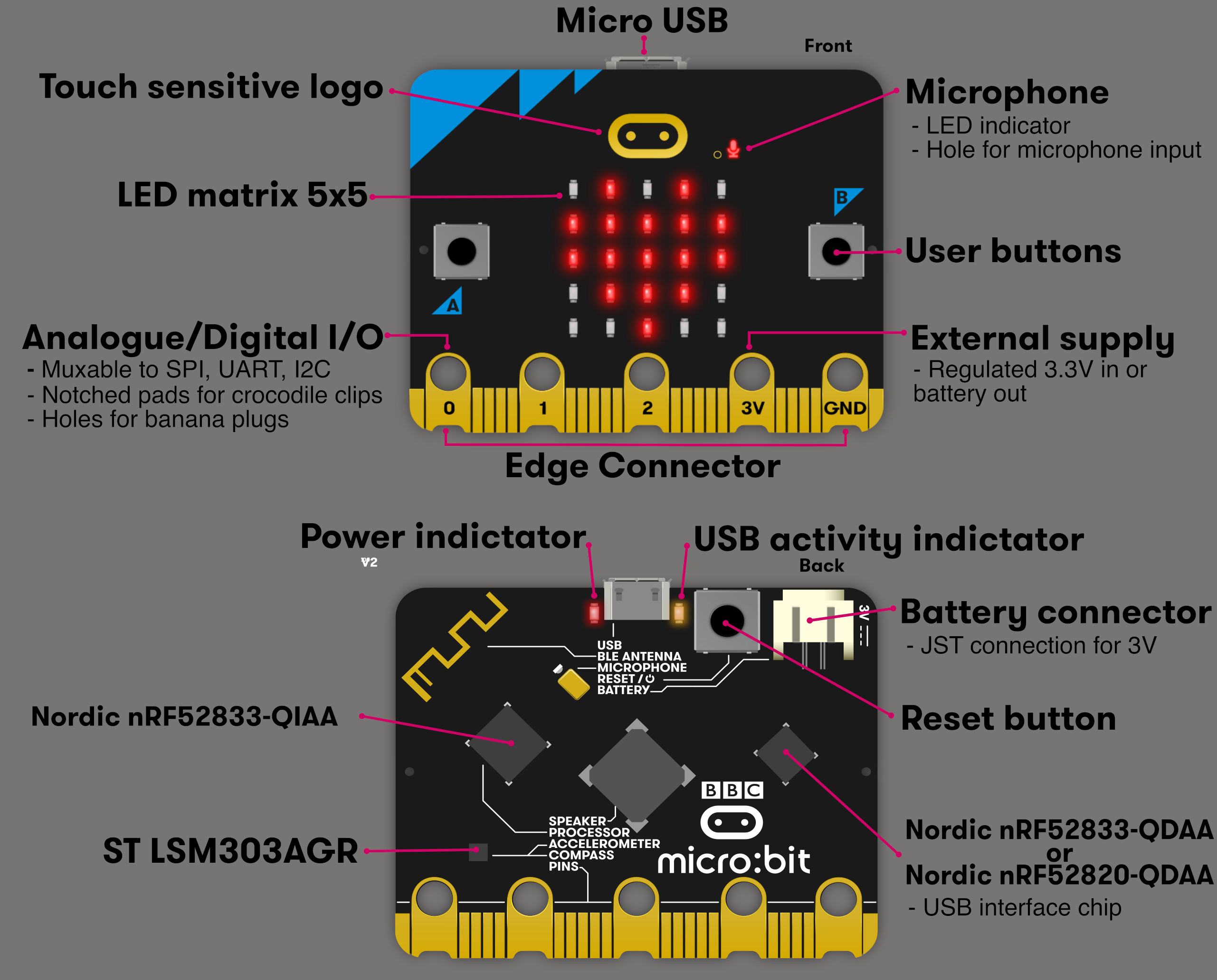
- Buttons A and B: These are two user buttons you can use as input. For example, if you're making a simple game, you can use them to move a player or trigger actions.
- 5x5 LED Matrix: This grid of red LEDs can display text, symbols, or animations.
- Edge Connector Pins: Pins labeled 0, 1, 2, 3V, and GND let you connect external components like sensors, LEDs, or motors.
- Microphone: Used to detect sound levels or respond to audio input (This was the fun part when i first purchased the board)
- Speaker: You can play sounds and tones directly from the board.
- USB Connector: Used to connect the board to your computer for programming or power.
- Battery Connector: You can power the board using batteries when not plugged into USB (If you purchased with accessories, you will get the batter and the cable for this)
- BLE Antenna: Enables Bluetooth communication, so you can connect the board wirelessly to other devices.
Don't be bothered by other details at the moment.
Datasheets and Manuals
Datasheets and technical manuals are helpful for understanding the pin layout, electrical specifications, communication methods, and other details of hardware components.
-
Overview: This webpage "https://tech.microbit.org/hardware/2-0-revision/" provides an overview of each component in the microbit
-
nRF52833: As i mentioned earlier, the microbit utilizes the nRF52833 System-on-Chip (SoC). To understand how to configure its pins and manage input/output operations, it's essential to read the official product specification. You can access the document here.
-
LSM303AGR: A low-power 3-axis accelerometer and magnetometer sensor used for motion detection and orientation tracking. You can access its datasheet here
-
Schematic: This provides a detailed diagram showing the electrical connections and components of the device. The full schematic in PDF format is available on GitHub here. Detailed schematic information is also available on this webpage: https://tech.microbit.org/hardware/schematic/
Don't be overwhelmed by all the information here or in the document. We will take it step by step, starting with some fun exercises. You can always return later to explore the details at your own pace.
Development Environment
I am going to assume you already have Rust installed on your machine and that you know the basics. If not, it might be a bit challenging to follow along. I highly recommend learning the basics of Rust first, then coming back to this.
probe-rs
probe-rs is a toolkit for working with embedded ARM and RISC-V devices. It supports flashing firmware, debugging programs, and printing logs via various debug probes.
The project includes tools like:
- cargo-flash -quickly flash firmware to a target
- cargo-embed - open a full RTT terminal with support for multiple channels and command input
We will be using this to flash (i.e writing the code into the device and running it) our program onto the microbit and run it; also for debugging purposes.
You can find more information here. Please see the installation guide for setup instructions.
You can confirm the installation was successful by running this command:
cargo embed --version
Cross compilation target
Since the micro:bit runs on an ARM Cortex-M processor, we need to compile our Rust code for that architecture. This requires setting up a specific compilation target for cross-compiling.
For the micro:bit v2, the correct target is:
thumbv7em-none-eabihf
You can add this target using Rust's built-in toolchain manager:
rustup target add thumbv7em-none-eabihf
Once added, you can specify this target when building or flashing your project. For example:
cargo build --release --target thumbv7em-none-eabihf
Or it will be used automatically when running tools like cargo embed, as long as your project is configured correctly(this part we will get into later chapter).
Quick Start
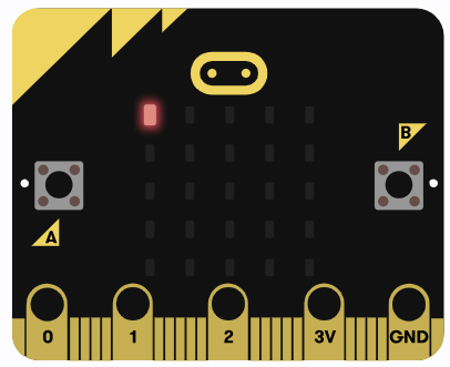
Before diving into the theory and concepts of how everything works, let's jump straight into action. Use this simple code to create blink effect on the LED Matrix of the microbit.
The microbit has a 5x5 LED matrix that you can control to show patterns, characters, or animations. Each LED can be turned on or off to create different effects.
The Full code
Don't worry about the code for now - we will explain it in the next chapter. This code simply turns on the LED at the top-left corner, then turns it off after a short delay in a loop; this will create a blinking effect.
#![no_std]
#![no_main]

use embedded_hal::{delay::DelayNs, digital::OutputPin};
use microbit::{board::Board, hal::timer::Timer};

use cortex_m_rt::entry;

#[panic_handler]
fn panic(_: &core::panic::PanicInfo) -> ! {
    loop {}
}

#[entry]
fn main() -> ! {
    let mut board = Board::take().unwrap();
    let mut timer = Timer::new(board.TIMER0);

    let _ = board.display_pins.col1.set_low();
    let mut row1 = board.display_pins.row1;

    loop {
        let _ = row1.set_low();
        timer.delay_ms(500);
        let _ = row1.set_high();
        timer.delay_ms(500);
    }
}
Clone the Quick start project
You can clone the quick start project I created and navigate to the project folder and run it.
git clone https://github.com/ImplFerris/microbit-projects
cd microbit-projects/bsp/blinky
Flash - Run Rust Run
All that's left is to flash the code onto our device and watch it go!
Run the following command from your project folder:
#![allow(unused)]
fn main() {
cargo embed
}
The first LED in the top row of the display matrix should start blinking now. If you are able to flash successfully and see the blinking effect, congratulations!
Abstraction Layers
When working with embedded Rust, you will often come across terms like PAC, HAL, and BSP. These are the different layers that help you interact with the hardware. Each layer offers a different balance between flexibility and ease of use.
Let's start from the highest level of abstraction down to the lowest.
Note: Throughout this book, we will use whichever crate best fits the needs of each exercise. Some exercises may use a Board Support Package (BSP), while others may rely directly on the Hardware Abstraction Layer (HAL).
Board Support Package (BSP)
A BSP, also referred as Board Support Crate in Rust, tailored to specific development boards. It combines the HAL with board-specific configurations, providing ready to use interfaces for onboard components like LEDs, buttons, and sensors. This allows developers to focus on application logic instead of dealing with low-level hardware details. micro:bit also has Board support crate, you can find it here.
In the quick start chapter, we in fact used this.
Example code snippet for BSP
// Turn on the first LED in the first row
use cortex_m_rt::entry;
use embedded_hal::digital::OutputPin;
use microbit::board::Board;

#[entry]
fn main() -> ! {
    let mut board = Board::take().unwrap();

    let _ = board.display_pins.col1.set_low();
    let mut row1 = board.display_pins.row1;
    let _ = row1.set_high();

    loop {}
}
Hardware Abstraction Layer (HAL)
The HAL sits just below the BSP level. If you work with boards like the Raspberry Pi Pico or ESP32 based boards, you'll mostly use the HAL level. In this book, after some BSP examples, we will focus more on HAL.
The HAL builds on top of the PAC and provides simpler, higher-level interfaces to the microcontroller's peripherals. Instead of handling low-level registers directly, HALs offer methods and traits that make tasks like setting timers, setting up serial communication, or controlling GPIO pins easier.
HALs usually implement the embedded-hal traits, which are standard, platform-independent interfaces for peripherals like GPIO, SPI, I2C, and UART. This makes it easier to write drivers and libraries that work across different hardware as long as they use a compatible HAL.
Later, we will explore the nrf52833-hal. As you can see, this crate is no longer specific to a dev board but instead tied to the nRF52833 chip. So if another dev board uses the same chip, you can mostly use the same code.
Example code snippet for HAL
// Turn on the first LED in the first row
use cortex_m_rt::entry;
use embedded_hal::digital::OutputPin;
use nrf52833_hal::gpio::{p0, Level};
use nrf52833_hal::pac::Peripherals;

#[entry]
fn main() -> ! {
    let p = Peripherals::take().unwrap();
    let port0 = p0::Parts::new(p.P0);
    let mut col1 = port0.p0_28.into_push_pull_output(Level::High);
    let mut row1 = port0.p0_21.into_push_pull_output(Level::Low);

    col1.set_low().unwrap();
    row1.set_high().unwrap();

    loop {}
}
If you compare this to BSP code, you'll find BSP code easier to read. But at the HAL level, things get more complex. Unless you have some background in embedded programming or electronics, these terms might seem strange. Don't worry; we'll cover all this step by step later.
NOTE:
The layers below the HAL are rarely used directly. In most cases, the PAC is accessed through the HAL, not on its own. Unless you are working with a chip that does not have a HAL available, there is usually no need to interact with the lower layers directly. In this book, we will focus on the BSP and HAL layers.
Peripheral Access Crate (PAC)
PACs are the lowest level abstraction. They are auto generated crates that give type-safe access to a microcontroller's peripherals. These crates are usually created from the manufacturer's SVD (System View Description) file using tools like svd2rust. PACs give you a structured and safe way to work with hardware registers directly.
Example code snippet for PAC
// Turn on the first LED in the first row

use cortex_m_rt::entry;
use nrf52833_pac::Peripherals;

#[entry]
fn main() -> ! {
    let p = Peripherals::take().unwrap();
    let gpio0 = p.P0;

    gpio0.pin_cnf[21].write(|w| {
        w.dir().output();
        w.input().disconnect();
        w.pull().disabled();
        w.drive().s0s1();
        w.sense().disabled();
        w
    });
    gpio0.pin_cnf[28].write(|w| {
        w.dir().output();
        w.input().disconnect();
        w.pull().disabled();
        w.drive().s0s1();
        w.sense().disabled();
        w
    });

    gpio0.outclr.write(|w| w.pin28().clear());
    gpio0.outset.write(|w| w.pin21().set());

    loop {}
}
Raw MMIO
Raw MMIO (memory-mapped IO) means directly working with hardware registers by reading and writing to specific memory addresses. This approach mirrors traditional C-style register manipulation and requires the use of unsafe blocks in Rust due to the potential risks involved. We will not touch this area; I haven't seen anyone using this approach, and even if they do, it's outside the scope of this book.
Example code snippet
// Turn on the first LED in the first row

#![no_main]
#![no_std]

extern crate panic_halt as _;

use nrf52833_pac as _;

use core::mem::size_of;
use cortex_m_rt::entry;

const GPIO_P0: usize = 0x5000_0000;

const PIN_CNF: usize = 0x700;
const OUTSET: usize = 0x508;
const OUTCLR: usize = 0x50c;

const DIR_OUTPUT: u32 = 0x1;
const INPUT_DISCONNECT: u32 = 0x1 << 1;
const PULL_DISABLED: u32 = 0x0 << 2;
const DRIVE_S0S1: u32 = 0x0 << 8;
const SENSE_DISABLED: u32 = 0x0 << 16;

#[entry]
fn main() -> ! {
    let pin_cnf_21 = (GPIO_P0 + PIN_CNF + 21 * size_of::<u32>()) as *mut u32;
    let pin_cnf_28 = (GPIO_P0 + PIN_CNF + 28 * size_of::<u32>()) as *mut u32;
    unsafe {
        pin_cnf_21.write_volatile(
            DIR_OUTPUT | INPUT_DISCONNECT | PULL_DISABLED | DRIVE_S0S1 | SENSE_DISABLED,
        );
        pin_cnf_28.write_volatile(
            DIR_OUTPUT | INPUT_DISCONNECT | PULL_DISABLED | DRIVE_S0S1 | SENSE_DISABLED,
        );
    }

    let gpio0_outset = (GPIO_P0 + OUTSET) as *mut u32;
    let gpio0_outclr = (GPIO_P0 + OUTCLR) as *mut u32;
    unsafe {
        gpio0_outclr.write_volatile(1 << 28);
        gpio0_outset.write_volatile(1 << 21);
    }

    loop {}
}
Reference
- The code snippets of PAC and Raw MMIO is taken from the Google's Comprehensive Rust book
Micro:bit Project Template with cargo-generate
To simplify project setup and learning for the micro:bit, I've created a reusable project template. We'll use the cargo-generate tool to get started.
What is
cargo-generate?
cargo-generateis a tool that helps you quickly create new Rust projects using pre-made templates, avoiding boilerplate setup and code.
You can learn more about it here.
Prerequisites
Before installing cargo-generate, make sure you have libssl-dev installed.
On Ubuntu or Debian-based systems, run:
sudo apt install libssl-dev
Then, install cargo-generate with:
cargo install cargo-generate
Step 1: Generate a New Project
Once cargo-generate is installed, you can generate a new project using the following command:
cargo generate --git https://github.com/ImplFerris/mb2-template.git --rev 88d339b
Note: I have included the specific rev (revision) value in the cargo generate command to ensure the setup is reproducible. Without it, future changes to the template might break compatibility with this tutorial.
You will be prompted to enter a project name.
You will then prompted to choose "BSP" or "HAL";
After that, a new directory with that name will be created. Navigate into it:
cd your-project-name
Now you're ready to build and run your micro:bit project.
To flash and run the code on the micro:bit, use:
cargo embed
Help & Troubleshooting
If you face any bugs, errors, or other issues while working on the exercises, here are a few ways to troubleshoot and resolve them.
1. Compare with Working Code
Check the complete code examples or clone the reference project for comparison. Carefully review your code and Cargo.toml dependency versions. Look out for any syntax or logic errors. If a required feature is not enabled or there is a feature mismatch, make sure to enable the correct features as shown in the exercise.
If you find a version mismatch, either adjust your code(research and find a solution; it's a great way for you to learn and understand things better) to work with the newer version or update the dependencies to match the versions used in the tutorial.
2. Search or Report GitHub Issues
Visit the GitHub issues page to see if someone else has encountered the same problem: https://github.com/ImplFerris/microbit-book/issues?q=is%3Aissue
If not, you can raise a new issue and describe your problem clearly.
3. Ask the Community
The Rust Embedded community is active in the Matrix Chat. The Matrix chat is an open network for secure, decentralized communication.
Here are some useful Matrix channels related to topics covered in this book:
-
Embedded Devices Working Group
#rust-embedded:matrix.org
General discussions around using Rust for embedded development. -
Nordic Chips / nRF Development
#nrf-rs:matrix.org
Focused on using Rust with Nordic Semiconductor chips (like the nRF52 series used in micro:bit v2). -
Debugging with Probe-rs
#probe-rs:matrix.org
For support and discussion around the probe-rs debugging toolkit. -
Embedded Graphics
#rust-embedded-graphics:matrix.org
For working withembedded-graphics, a drawing library for embedded systems.
You can create a Matrix account and join these channels to get help from experienced developers.
You can find more community chat rooms in the Awesome Embedded Rust - Community Chat Rooms section.
4. Discord
There is an unofficial Discord community for Embedded Rust where you can ask questions, discuss topics, share your experiences, and showcase your projects. It is especially useful for learners and general discussion.
Keep in mind that most HAL and embedded ecosystem maintainers are more active on Matrix. Still, this Discord server can be a good place to learn and interact with others.
Join here: https://discord.gg/NHenanPUuG
Project Walkthrough
We have successfully flashed and run our first program, which creates a blinking effect. However, we have not yet explored the code or the project structure in detail. In this section, we will recreate the same project from scratch instead of using the template. I will explain each part of the code and configuration along the way. Are you ready for the challenge?
Create a Fresh Project
We will start by creating a standard Rust binary project. Use the following command:
cargo new blinky
At this stage, the project will contain the usual files as expected.
├── Cargo.toml
└── src
    └── main.rs
Our goal is to reach the following final project structure:
├── .cargo
│   └── config.toml
├── Cargo.toml
├── Embed.toml
├── memory.x
└── src
    └── main.rs
Dependencies
We will begin by adding the required dependencies for the project. Update the Cargo.toml file with the following entries:
cortex-m-rt = "0.7.3"
microbit-v2 = "0.15.0"
embedded-hal = "1.0.0"
We are using the Board Support Package (BSP) approach, so the microbit-v2 crate provides the board support layer for the micro:bit v2.
We will also take a closer look at the other two dependencies, cortex-m-rt and embedded-hal, in separate sections where I can explain their roles in more detail.
Runtime
Let's start with the first dependency cortex-m-rt. This crate provides the startup code and a minimal runtime for Cortex-M microcontrollers. As you may already know, our micro:bit is also based on a Cortex-M core.
Why do we need?
In embedded development, there is typically no underlying OS (though specialized operating systems for microcontrollers do exist). This means you must set up everything yourself: how the program starts, how memory is initialized, and how the device responds to events like button presses or incoming data.
To make all of this work, we will use a runtime crate. A runtime in embedded Rust provides the minimal startup code that runs before your main function, sets up memory (like the stack and heap), and helps you define how your program should react to interrupts.
Entry point
From a developer's perspective, it might seem like the main function is the first code executed when a program runs. However, this isn't actually the case. In most languages, a runtime system sets up the environment before eventually calling main.
In contrast, embedded systems like the micro:bit don't have a standard runtime. Instead, we use a custom runtime, such as the one provided by the cortex-m-rt crate. In this setup, we need to explicitly specify the program's entry point. For the micro:bit v2, it is done using the #[entry] attribute provided by cortex-m-rt, which tells the runtime which function to run first.
no_main
We will use the #![no_main] directive to tell the Rust compiler that we don't want to use the normal program entry point. Instead, we will provide our own entry point and main function.
By adding #![no_main], we disable the default program's startup logic, allowing the embedded runtime (like cortex-m-rt) to take control.
Modify code
Let's update our program to include these attributes. Open your project in a code editor and modify the src/main.rs file as follows:
#![no_std]
#![no_main]

use cortex_m_rt::entry;

#[entry]
fn main() {
    println!("Hello, world!");
}
After you update the code, you will likely see an error from rust-analyzer saying:
#![allow(unused)]
fn main() {
error: `#[entry]` function must have signature `[unsafe] fn() -> !`
}
This happens because the #[entry] function is required to never return. It must have the return type ! (called the "never" type) to show that the program runs indefinitely and does not exit. This requirement is critical in embedded or bare-metal systems because, unlike applications running on a traditional operating system, there is no OS to hand control back to once the program finishes.
To fix this, update your main function signature to:
#[entry]
fn main() -> ! {
    loop {
        // keep running forever
    }
}
If you have Clippy enabled, you might see a warning saying "empty loop {} wastes CPU cycles." You can safely ignore this warning for now.
References:
-
cortex_m_rt crate document: https://docs.rs/cortex-m-rt/latest/cortex_m_rt/index.html
-
A Freestanding Rust Binary - Start attribute: https://os.phil-opp.com/freestanding-rust-binary/#the-start-attribute
Embedded HAL
The embedded-hal crate is the heart of the embedded Rust ecosystem. It provides a foundation of common hardware abstraction traits for things like I/O, SPI, I2C, PWM, and timers. These traits create a standard interface that lets high-level drivers, like those for sensors or wireless devices, work across different hardware platforms.
Because drivers are written as generic libraries on top of embedded-hal, they can support a wide range of targets, from Cortex-M and AVR microcontrollers to embedded Linux systems.
Example
In the quick-start example, we used embedded-hal traits to control pins and timers on a micro:bit board. The set_low and set_high functions come from the OutputPin trait, and the delay_ms function comes from the DelayNs trait, both part of embedded-hal.
You might still wonder why not just write set_low and set_high functions directly without using traits. To illustrate this, consider two versions of a simple function that turns an LED on or off:
#![allow(unused)]
fn main() {
// Example with a concrete pin type (imaginary MicrobitPin)
struct MicrobitPin;

impl MicrobitPin {
    fn set_low(&mut self) {
        // Hardware-specific code to set the pin low
    }
    fn set_high(&mut self) {
        // Hardware-specific code to set the pin high
    }
}
}
Your application/driver code:
#![allow(unused)]
fn main() {
fn control_led_concrete(pin: &mut MicrobitPin, light_up: bool) {
    if light_up {
        pin.set_low();
    } else {
        pin.set_high();
    }
}
}
This is your application code to control the LED. This function only works with the MicrobitPin type. What if you want to port your application or driver to support other microcontrollers? Then you have to write a new crate or add separate logic to handle those.
#![allow(unused)]
fn main() {
fn control_led_another_mcu(pin: &mut AnotherMcuPin, light_up: bool) {
    if light_up {
        pin.set_low();
    } else {
        pin.set_high();
    }
}
}
Now let's compare it with the embedded-hal trait-based approach:
#![allow(unused)]
fn main() {
use embedded_hal::digital::OutputPin;

// This function works with any pin type that implements OutputPin
fn control_led_generic<P: OutputPin>(pin: &mut P, light_up: bool) {
   if light_up {
       let _ = pin.set_low();
   } else {
       let _ = pin.set_high();
   }
}
}
By using the OutputPin trait, this function works on any hardware platform that implements the trait. This makes your code reusable and portable without rewriting it for every board.
This trait-based approach is why embedded-hal is so important in embedded Rust - it provides a common interface that works across different hardware.
no_std Rust environment
When you write a regular Rust program, you get access to the full standard library (std). It gives you features like heap allocation, threads, file systems, and networking. But all these features assume one thing: there's an operating system underneath.
In embedded systems, we usually don't have an operating system. There's no filesystem. No network stack. No heap allocator unless you bring your own. You are running directly on the hardware.
That's where no_std comes in.
By adding this line at the top of your code:
#![allow(unused)]
#![no_std]
fn main() {
}
You tell the Rust compiler: "I don't need the standard library. I'll manage with just the core language features."
Rust will now link only the minimal core crate, which includes the essentials: basic types, error handling, and so on. This is enough to write logic for most embedded applications.
Modify code
Let's update our program to include this directive. Open your project in a code editor and modify the src/main.rs file as follows:
#![no_std]
#![no_main]

use cortex_m_rt::entry;

#[entry]
fn main() -> ! {
    loop {}
}
LED Matrix
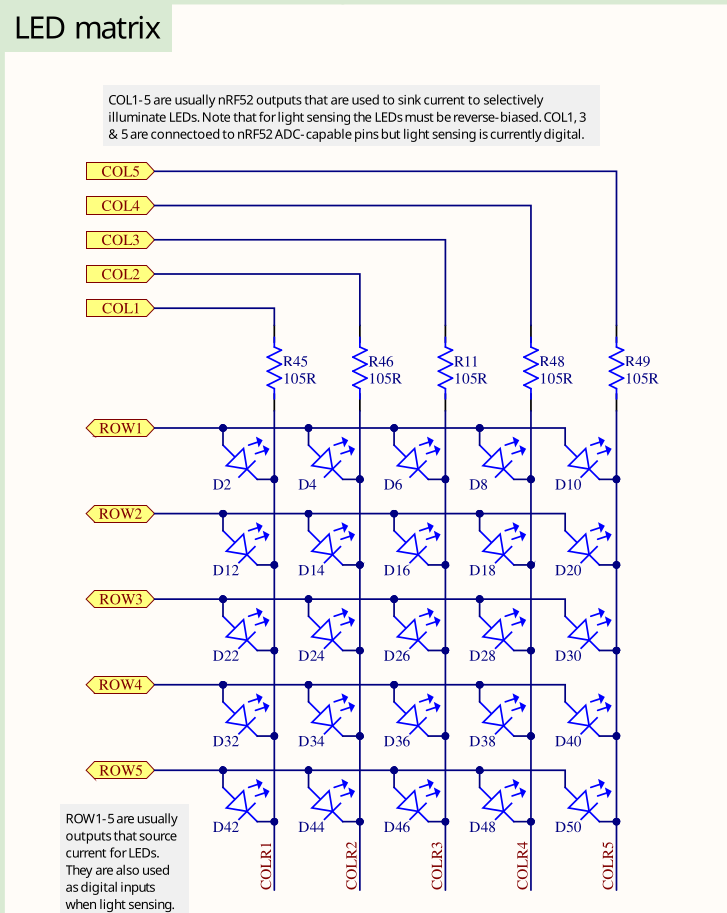
On the micro:bit board, the onboard LEDs are arranged in a 5x5 matrix, giving a total of 25 LEDs. Unlike other boards that have just one or two LEDs each connected to dedicated GPIO (General Purpose I/O) pins, the micro:bit can't use a separate GPIO pin for every LED. If it did, all the GPIO pins would be used up just for the LEDs, leaving none available for things like sensors or other inputs.
Multiplexing: Sharing Pins to Control Many LEDs
Instead of using one pin per LED, the micro:bit's 5x5 matrix uses only 10 GPIO pins: 5 for rows and 5 for columns. The LEDs are wired in a grid where each LED sits at the intersection of a row and a column.
- Row pins provide power (set to logic HIGH).
- Column pins provide a path to ground (set to logic LOW).
By selecting the right row and column, the microcontroller can light up a single LED.
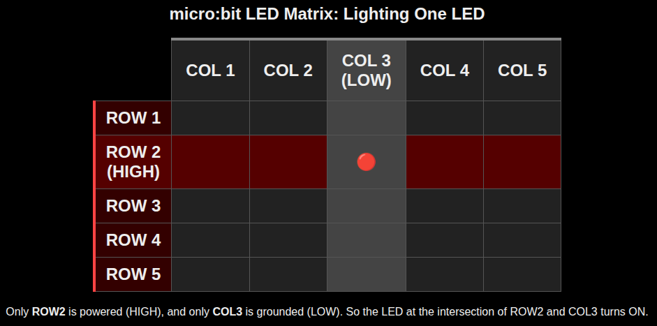
How Lighting a Single LED Works
To turn on a specific LED, for example the one in row 2 and column 3:
- We will set the row 2 to HIGH. This supplies voltage to that row.
- We will set the column 3 to LOW. This connects that column to ground.
- The current flows from the row through the LED at that intersection to the column, lighting it up.
Lighting Multiple LEDs Using Fast Scanning
When we want to light up several LEDs in different rows, the micro:bit turns on one row at a time, very quickly.
For example:
- It activates row 1 and sets the appropriate columns LOW to light some LEDs.
- Then it deactivates row 1, activates row 2, and updates the column pins.
- This continues rapidly for all 5 rows.
This scanning happens so fast (dozens of times per second) that our eyes cannot detect the flickering. Instead, we see a steady image. This effect is known as persistence of vision.
NOTE: You don't need to worry about how this scanning is done internally. In code, we just set the required columns to LOW and the target row to HIGH. The micro:bit takes care of the rest.
GPIO pin mapping
This info isn't very useful for this chapter, but later when we work with HAL, we'll need to know which row and column match which pin.
As per the micro:bit V2 schematic, the LED matrix pins connect to the following GPIOs on the nRF52833 microcontroller:
| Matrix Role | Role | Port | Pin |
|---|---|---|---|
| ROW1 | Source | P0 | 21 |
| ROW2 | Source | P0 | 22 |
| ROW3 | Source | P0 | 15 |
| ROW4 | Source | P0 | 24 |
| ROW5 | Source | P0 | 19 |
| COL1 | Sink | P0 | 28 |
| COL2 | Sink | P0 | 11 |
| COL3 | Sink | P0 | 31 |
| COL4 | Sink | P1 | 05 |
| COL5 | Sink | P0 | 30 |
Reference
- uBit.display (for micro:bit v1) : This is for micro:bit v1. The LED pin layout is different in micro:bit v2, so it won't match exactly.
Implementing the Core logic
We started with a fresh project, and in the last few chapters, we mainly focused on theory. That might have felt a bit dry (or maybe exciting, depending on your perspective). In this section, we will switch gears and focus on writing actual code to keep things hands-on and engaging.
Keep in mind: the code will not compile or run just yet, since we still need to set up a few configurations specific to the microcontroller. But don't worry! We will take it step by step. For now, let's concentrate on building the core logic.
Imports
Let's begin with the necessary imports. We will use the DelayNs and OutputPin traits provided by the embedded HAL. The DelayNs trait allows us to add delays between turning the LED on and off, creating the visible blinking effect;without it, the LED would toggle too fast to see.
As mentioned earlier, the OutputPin trait provides methods(set_low, set_high) to change the state of a microcontroller's output pin. We will use it to toggle the output pin connected to our target LED between low and high states.
#![allow(unused)]
fn main() {
use embedded_hal::{delay::DelayNs, digital::OutputPin};
use microbit::{board::Board, hal::timer::Timer};
}
We will also import the necessary structs from the microbit crate.
Main function
Now let's update the main function.
First, we acquire access to the micro:bit board peripherals by calling:
#![allow(unused)]
fn main() {
let mut board = Board::take().unwrap();
}
This line gives us a singleton instance of the board, which contains handles to all the microcontroller's hardware peripherals like pins, timers, and more. The take() method returns an Option because the peripherals can only be taken once during the program's lifetime to prevent multiple mutable accesses that could cause conflicts or data races. Calling unwrap() here is safe because we expect to call take() only once in our program.
After obtaining the board peripherals, the next step is to create a timer instance:
#![allow(unused)]
fn main() {
let mut timer = Timer::new(board.TIMER0);
}
Display Matrix
As we learned in the LED Matrix section, to turn on the LED at first row and first column, we will set column 1 to LOW (i.e connecting it to ground). Then inside a loop, we will keep toggling row 1 between HIGH(i.e connecting it to power) and LOW, with a 500 ms delay in between to create a blinking effect.
#![allow(unused)]
fn main() {
let _ = board.display_pins.col1.set_low();
let mut row1 = board.display_pins.row1;

loop {
    let _ = row1.set_low();
    timer.delay_ms(500);
    let _ = row1.set_high();
    timer.delay_ms(500);
}
}
Panic Handler
I assume you already have a basic idea of what a panic is in Rust. When a panic happens, the program does not immediately exit. Instead, control is passed to the panic handler provided by the standard lib. By default, it starts unwinding the stack of the panicking thread. But if the user has chosen to abort on panic, then the program will terminate right away without unwinding.
If we try to build the program at this stage, we will see this error:
error: `#[panic_handler]` function required, but not found

error: unwinding panics are not supported without std
This means we need to define a custom panic handler, since we're not using the standard library.
Panic handler in no_std
In a no_std environment, we have to provide our own panic handler. There are crates that do this for us, and we can pick one based on the behavior we want.
For example:
-
If we want the program to abort immediately, we can use the
panic-abortcrate. -
If we want the program (or the current thread) to halt by entering an infinite loop, we can use the
panic-haltcrate.
If you check the source code of these crates, you will notice they are just simple functions.
You can either import one of these crates like this:
#![allow(unused)]
fn main() {
use panic_halt as _;
}
Or define the panic handler function yourself. That's what we're going to do.
The function must be marked with the #[panic_handler] attribute, and it must accept a reference to core::panic::PanicInfo. It should never return, so its return type is !.
Here's the function (equivalent to what panic-halt provides). Let's update the src/main.rs file and include the following code
#![allow(unused)]
fn main() {
#[panic_handler]
fn panic(_: &core::panic::PanicInfo) -> ! {
    loop {}
}
}
Reference
-
Panicking section in The Embedded Rust book
-
panic_handler section in The Rustonomicaon
-
Bare-metal target for CPUs in the Armv7E-M architecture family
Target
Let's try building it. Wait, it still doesn't build and shows this error:
rustc: found duplicate lang item `panic_impl`
the lang item is first defined in crate `std` (which `test` depends on)
The solution is simple: you just need to specify the target platform explicitly. When you don't specify the target, the compiler builds for your host machine by default, which includes its own panic handler from std. This causes a conflict because your code also provides a panic handler, leading to the duplicate lang item error.
Since our micro:bit uses an ARM Cortex-M4 32-bit processor with a Floating Point Unit (FPU), the correct target to use is thumbv7em-none-eabihf. We already added this target in the quickstart section.
So we can simply build it using the following command:
cargo build --target thumbv7em-none-eabihf
.cargo/config.toml
There are two things to fix. First, the code editor might still highlight the panic function and show a duplicate error. Second, it's not convenient to type the target every time we build.
To solve this, we can create a config.toml file inside the .cargo directory and set the default target there.
Run the following commands from the root of your project (the same directory where Cargo.toml is located) to create the .cargo directory. Then create the config.toml inside the .cargo directory.
mkdir .cargo
cd .cargo
Update the config.toml with the following content:
[build]
target = "thumbv7em-none-eabihf"
Now try running the build command without specifying the target. It should compile successfully:
cargo build
Let's take a look at the src/main.rs code we have up to this point.
#![no_std]
#![no_main]

use cortex_m_rt::entry;

use embedded_hal::{delay::DelayNs, digital::OutputPin};
use microbit::{board::Board, hal::timer::Timer};

#[panic_handler]
fn panic(_: &core::panic::PanicInfo) -> ! {
    loop {}
}

#[entry]
fn main() -> ! {
    let mut board = Board::take().unwrap();
    let mut timer = Timer::new(board.TIMER0);

    let _ = board.display_pins.col1.set_low();
    let mut row1 = board.display_pins.row1;

    loop {
        let _ = row1.set_low();
        timer.delay_ms(500);
        let _ = row1.set_high();
        timer.delay_ms(500);
    }
}
Are we there yet?
We have successfully been able to build the program, but are we ready to flash it (write it into the micro:bit's persistent memory and run it)? Not yet but we are close. There are a few more steps we need to complete before that.
If you try running cargo embed now, you'll see this error:
...other warnings...
WARN probe_rs::flashing::loader: No loadable segments were found in the ELF file.
Error No loadable segments were found in the ELF file.
This error means that the compiler created a file (ELF file) that doesn't have any actual code or data for the flasher to write into the micro:bit. In other words, the file is empty from the flasher's point of view.
Why did this happen? Because the compiler doesn't know where in memory to place the program. Even though we are using the cortex-m-rt crate (which gives us startup code and other support), the linker still needs to know how the micro:bit's memory is laid out. Without this information, it skips putting the actual program into the output file.
Fixing the Error
To solve this, we need to tell the compiler to use a special script called link.x. This script is provided by the cortex-m-rt crate and tells the compiler how to place code and data into memory.
Update the .cargo/config.toml with this:
[target.thumbv7em-none-eabihf]
rustflags = ["-C", "link-arg=-Tlink.x"]
This line adds a flag that tells the compiler: "Please use link.x to figure out the memory layout."
memory.x
According to the cortex-m-rt crate documentation, we need a file called memory.x to define the memory layout of the microcontroller. This file tells the linker where the flash and RAM start, and how large they are.
So... where is it?
If you try to flash the device at this stage itself, the program should get flashed and run on the micro:bit. That's because the memory.x file is automatically included from the nrf52833-hal crate. You can see it here: https://github.com/nrf-rs/nrf-hal/blob/master/nrf52833-hal/memory.x
However, it's better to define the memory.x file in our own project to avoid any kind of ambiguity. So in the project root folder, create a file named memory.x with the following content:
MEMORY
{
  FLASH : ORIGIN = 0x00000000, LENGTH = 512K
  RAM : ORIGIN = 0x20000000, LENGTH = 128K
}
This tells the linker where the flash and RAM start, and how much memory is available.
ORIGIN = 0x00000000means the flash memory begins at address0x00000000.LENGTH = 512Kmeans the flash memory size is 512 kilobytes (512 × 1024 bytes).ORIGIN = 0x20000000means the RAM starts at address0x20000000.LENGTH = 128Kmeans the RAM size is 128 kilobytes.
These addresses and sizes are based on the nRF52833 document.
At this point, your project folder should look like this:
├── .cargo
│   └── config.toml
├── Cargo.toml
├── memory.x
└── src
    └── main.rs
Flash it
Now try building and flashing your program:
cargo flash

# OR

cargo embed
This time, the ELF file will contain valid loadable segments, and the flasher will be able to write it into the micro:bit's flash memory.
If all goes well, your program should now be running on the micro:bit! You should see the blinking effect on the first LED.
Reference
Fun with LED
Phew... that was a long chapter, and it might have felt a bit overwhelming if you're just getting started. But now, let's take a break and have some fun with the LED matrix!
The BSP gives us a simple and beginner-friendly API. You can just define a 2D array that matches the actual layout of the LED matrix on the micro:bit. Use 1 to turn an LED on and 0 to turn it off. The BSP takes care of everything else behind the scenes.
This is an example LED matrix displaying a heart shape. I tried creating a Ferris (crab) shape, but it didn't quite look right, and I'd have to convince you it was a crab. So, it's better to just show a heart shape instead.
#![allow(unused)]
fn main() {
// LED matrix for heart shape
let led_matrix = [
    [0, 1, 0, 1, 0],
    [1, 1, 1, 1, 1],
    [1, 1, 1, 1, 1],
    [0, 1, 1, 1, 0],
    [0, 0, 1, 0, 0],
];
}
Display
The BSP provides a Display struct that you can initialize using the display_pins from the board. It offers a few useful functions, the most important ones being show and clear. The show function takes a 2D array and turns on the LEDs based on the values you provide. If you're curious about how it works under the hood, you can check out the source code here.
Create Project from template
We will no longer create .cargo/config.toml, memory.x, or manually add dependencies (only the basic dependencies) every time we start a new project. Instead, we will use a template-based approach to make project setup much easier.
To generate a new project using the template, run the following command:
cargo generate --git https://github.com/ImplFerris/mb2-template.git --rev 88d339b
When prompted for a project name, enter something like led-matrix.
When it prompts to select "BSP" or "HAL", select "BSP".
Once the project is created, update src/main.rs with the following code.
The full code
#![no_std]
#![no_main]

use embedded_hal::delay::DelayNs;
use microbit::{board::Board, display::blocking::Display, hal::timer::Timer};

use cortex_m_rt::entry;

#[panic_handler]
fn panic(_: &core::panic::PanicInfo) -> ! {
    loop {}
}

#[entry]
fn main() -> ! {
    let board = Board::take().unwrap();

    let mut timer = Timer::new(board.TIMER0);

    let mut display = Display::new(board.display_pins);
    let led_matrix = [
        [0, 1, 0, 1, 0],
        [1, 1, 1, 1, 1],
        [1, 1, 1, 1, 1],
        [0, 1, 1, 1, 0],
        [0, 0, 1, 0, 0],
    ];
    loop {
        display.show(&mut timer, led_matrix, 1000);
        display.clear();
        timer.delay_ms(1000);
    }
}
Everything in this code is pretty straightforward and simple, except for one thing: what is the third argument to show function, the one where we pass 1000?
It is called duration_ms, but what is that duration used for? No, it is not for the blinking effect. We already handle blinking separately using:
#![allow(unused)]
fn main() {
display.clear();
timer.delay_ms(1000);
}
So what is duration_ms really doing?
As we learned earlier, the micro:bit's 5x5 LED matrix is multiplexed. Only one row is turned on at a time, and the columns are set based on the image. Internally show function goes through each row, lights up the correct LEDs, waits a bit using delay.delay_us(...), then moves to the next row.
This scanning happens so quickly that it looks like the whole image is being displayed at once. The duration_ms value tells the display how long to keep repeating this scan.
In short: duration_ms(third argument) controls how long the image stays on the screen. You can adjust its value and see the effect.
Clone the existing project
You can also clone (or refer) project I created and navigate to the led-matrix folder.
git clone https://github.com/ImplFerris/microbit-projects
cd microbit-projects/bsp/led-matrix
Flash
You can flash the program into the micro:bit and should see the heart shape with blinking effect
cargo flash
Display Character
We were able to display a heart shape on the LED matrix. Now let's take it a step further and try showing some characters on it.
Let's start by displaying the character 'R'.
#![allow(unused)]
fn main() {
// Matrix for 'R'
[
    [1, 1, 1, 0, 0],
    [1, 0, 0, 1, 0],
    [1, 1, 1, 0, 0],
    [1, 0, 1, 0, 0],
    [1, 0, 0, 1, 0],
],
}
Create Project from template
To generate a new project using the template, run the following command:
cargo generate --git https://github.com/ImplFerris/mb2-template.git --rev 88d339b
When prompted for a project name, enter something like led-char.
Once the project is created, update src/main.rs with the following code.
The full code
#![no_std]
#![no_main]

use embedded_hal::delay::DelayNs;
use microbit::{board::Board, display::blocking::Display, hal::timer::Timer};

use cortex_m_rt::entry;

#[panic_handler]
fn panic(_: &core::panic::PanicInfo) -> ! {
    loop {}
}

#[entry]
fn main() -> ! {
    let board = Board::take().unwrap();

    let mut timer = Timer::new(board.TIMER0);

    let mut display = Display::new(board.display_pins);
    let led_matrix = [
        [1, 1, 1, 0, 0],
        [1, 0, 0, 1, 0],
        [1, 1, 1, 0, 0],
        [1, 0, 1, 0, 0],
        [1, 0, 0, 1, 0],
    ];
    loop {
        display.show(&mut timer, led_matrix, 1000);
        display.clear();
        timer.delay_ms(1000);
    }
}
Clone the existing project
You can also clone (or refer) project I created and navigate to the led-char folder.
git clone https://github.com/ImplFerris/microbit-projects
cd microbit-projects/bsp/led-char
Flash
You can flash the program into the micro:bit and should see the character
cargo flash
Scrolling Effect
In this section, we will create a scrolling effect for a single character. The character will scroll from right to left,disappear off the edge,and then reappear from the right again.
There is another BSP crate called microbit-bsp that provides built-in support for scrolling text. However, it uses the Embassy framework and asynchronous programming (async). Since we have not yet introduced Embassy or async concepts, we will avoid using that crate for now.
So for now, we will stick with the microbit-v2 crate and implement the scrolling logic ourselves.
Logic
You already know how to turn on the LED matrix using a 2D array. Now, try to think of a way to create a scrolling effect using that knowledge. There are multiple ways to do this. I encourage you to come up with your own logic first.
Below, I will show you one possible way to implement it. Keep in mind that this is just one approach, and it may not be the most efficient or elegant solution.
The Full code
#![no_std]
#![no_main]

use embedded_hal::delay::DelayNs;
use microbit::{board::Board, display::blocking::Display, hal::timer::Timer};
use cortex_m_rt::entry;

#[panic_handler]
fn panic(_: &core::panic::PanicInfo) -> ! {
    loop {}
}

#[entry]
fn main() -> ! {
    let board = Board::take().unwrap();
    let mut timer = Timer::new(board.TIMER0);
    let mut display = Display::new(board.display_pins);

    // 5x5 representation of 'R'
    let r_char = [
        [1, 1, 1, 0, 0],
        [1, 0, 0, 1, 0],
        [1, 1, 1, 0, 0],
        [1, 0, 1, 0, 0],
        [1, 0, 0, 1, 0],
    ];

    let mut offset = 0;

    loop {
        let mut frame = [[0; 5]; 5];

        for row in 0..5 {
            for col in 0..5 {
                let char_col = col as isize + offset - 4;

                if char_col >= 0 && char_col < 5 {
                    frame[row][col] = r_char[row][char_col as usize];
                } else {
                    frame[row][col] = 0;
                }
            }
        }

        display.show(&mut timer, frame, 500);
        timer.delay_ms(100);

        offset += 1;
        if offset > 8 {
            offset = 0;
        }
    }
}
We use a variable called offset to control which part of the character we show on the screen. As offset increases, the character moves to the left.
Scrolling with Offset
Our LED matrix is 5 columns wide. To scroll the character in from the right, move it fully across, and have it scroll out to the left, we need to allow for more than 5 steps.
Let's break it down:
-
The character starts completely off-screen on the right.
-
Then, it enters one column at a time.
-
It becomes fully visible in the center.
-
Finally, it moves out one column at a time to the left until it disappears.
We want to cover this full path:
[off-screen right] --> [entering display] --> [fully visible] --> [leaving display] --> [off-screen left]
This takes a total of 9 steps (offsets from 0 to 8):
| Offset | What happens on screen | How many columns of character are shown? | Character's position relative to the display |
|---|---|---|---|
| 0 | First column of the character appears at far right | 1 | Character is mostly off-screen to the right |
| 1 | First two columns appear | 2 | Character slides in more |
| 2 | First three columns appear | 3 | Half-visible |
| 3 | First four columns appear | 4 | Almost fully visible |
| 4 | Entire character is fully visible | 5 | Just as how it appears normally |
| 5 | First column starts disappearing from the left | 4 | Character starts sliding off to the left |
| 6 | Only middle and right side remain visible | 3 | More of character has exited |
| 7 | Only last part of the character remains | 2 | Nearly gone |
| 8 | Character is completely gone | 0 | Fully off-screen to the left |
Creating the Frame
We create a new 5x5 frame that we will send to the display. For each LED in the frame:
We calculate which column of the character (r_char) should be shown in that position. This is done with:
#![allow(unused)]
fn main() {
let char_col = col as isize + offset - 4;
}
This shifts the character slowly to the left.
We check if char_col is in the valid range (0 to 4). If yes, we copy that pixel from the character. If not, we set it to 0 (LED off).
Loop and Animate
We keep repeating this in a loop:
-
Show the current frame for 500 ms then wait 100 ms
-
Increase the offset
-
Reset offset back to 0 after it reaches 9
This gives the illusion that the character is scrolling from right to left and disappearing, then reappearing again.
offset, led matrix "col", char_col relation
Let's look at how these values change as the offset increases to understand it better.
offset = 0
Only the first column of R (index 0) is visible at the rightmost column.
char_col = col + offset - 4 = col - 4
col | 0 | 1 | 2 | 3 | 4 |
|---|---|---|---|---|---|
char_col | -4 | -3 | -2 | -1 | 0 |
. . . . #
. . . . #
. . . . #
. . . . #
. . . . #
Note: Using 0s and 1s directly can make it harder to see the shape clearly. So, in this illustration, the # symbol shows where an LED is turned on (i.e value 1). The dots (.) represent LEDs that are off (value 0).
offset = 1
Columns 3 and 4 show character columns 0 and 1 respectively.
char_col = col + 1 - 4 = col - 3
col | 0 | 1 | 2 | 3 | 4 |
|---|---|---|---|---|---|
char_col | -3 | -2 | -1 | 0 | 1 |
. . . # #
. . . # .
. . . # #
. . . # .
. . . # .
offset = 4
We will skip to the case where the offset is 4. At this point, the full character is completely visible on the display.
char_col = col + 4 - 4 = col
This means char_col and col are equal, so the frame array directly matches the original character array.
col | 0 | 1 | 2 | 3 | 4 |
|---|---|---|---|---|---|
char_col | 0 | 1 | 2 | 3 | 4 |
# # # . .
# . . # .
# # # . .
# . # . .
# . . # .
offset = 5
char_col = col + 5 - 4 = col + 1
col | 0 | 1 | 2 | 3 | 4 |
|---|---|---|---|---|---|
char_col | 1 | 2 | 3 | 4 | 5 |
# # . . .
. . # . .
# # . . .
. # . . .
. . # . .
Now, each char_col is one more than its corresponding col. When char_col becomes 5, it goes out of bounds (since our array only has indices from 0 to 4).
To prevent this, we add a bounds check. If char_col is outside the valid range, we fill that column with 0s. This creates the vanishing effect as the character scrolls out.
if char_col >= 0 && char_col < 5 {
    frame[row][col] = r_char[row][char_col as usize];
} else {
    frame[row][col] = 0;
}
The Full code
#![no_std]
#![no_main]

use embedded_hal::delay::DelayNs;
use microbit::{board::Board, display::blocking::Display, hal::timer::Timer};
use cortex_m_rt::entry;

#[panic_handler]
fn panic(_: &core::panic::PanicInfo) -> ! {
    loop {}
}

#[entry]
fn main() -> ! {
    let board = Board::take().unwrap();
    let mut timer = Timer::new(board.TIMER0);
    let mut display = Display::new(board.display_pins);

    // 5x5 representation of 'R'
    let r_char = [
        [1, 1, 1, 0, 0],
        [1, 0, 0, 1, 0],
        [1, 1, 1, 0, 0],
        [1, 0, 1, 0, 0],
        [1, 0, 0, 1, 0],
    ];

    let mut offset = 0;

    loop {
        let mut frame = [[0; 5]; 5];

        for row in 0..5 {
            for col in 0..5 {
                let char_col = col as isize + offset - 4;

                if char_col >= 0 && char_col < 5 {
                    frame[row][col] = r_char[row][char_col as usize];
                } else {
                    frame[row][col] = 0;
                }
            }
        }

        display.show(&mut timer, frame, 500);
        timer.delay_ms(100);

        offset += 1;
        if offset > 8 {
            offset = 0;
        }
    }
}
Clone the existing project
You can also clone (or refer) project I created and navigate to the led-scroll folder.
git clone https://github.com/ImplFerris/microbit-projects
cd microbit-projects/bsp/led-scroll
Flash
You can flash the program into the micro:bit.
cargo flash
Smiley Buttons
In this chapter, we will explore how to use the two onboard buttons of the micro:bit. The Smiley Buttons project is a great beginner-friendly exercise that introduces interactive input. By pressing the built-in buttons A and B, we will display different facial expressions on the micro:bit's LED screen.
-
Press button A to show a happy face 😊
-
Press button B to show a sad face 🙁
Understanding Buttons
🪝 From the micro:bit documentation:
Buttons operate in a typical inverted electrical mode, where a pull-up resistor ensures a logical ‘1’ when the button is released, and a logical ‘0’ when the button is pressed
This may sound a bit technical at first, so let us explain it more clearly.
When the button is not pressed, the micro:bit reads the input as a logical HIGH (i.e 1). This is due to the presence of a pull-up resistor, which maintains a high voltage level on the input pin.
When the button is pressed, the circuit is connected to ground, and the micro:bit reads a logical LOW (i.e 0).

Although pressing a button might intuitively seem like activating something, the hardware works in an inverted way. In code, we check for a LOW signal to detect when the button is pressed. Therefore, we will use the is_low() method on the button inputs to check whether it is being pressed.
Create Project from template
To generate a new project using the template, run the following command:
cargo generate --git https://github.com/ImplFerris/mb2-template.git --rev 88d339b
When prompted for a project name, enter something like smiley-buttons
When it prompts to select "BSP" or "HAL", select the option "BSP".
Matrix for emojis
Here is a 2D arrays representing the happy and sad faces.
#![allow(unused)]
fn main() {
let happy_face = [
        [0, 0, 0, 0, 0],
        [0, 1, 0, 1, 0],
        [0, 0, 0, 0, 0],
        [1, 0, 0, 0, 1],
        [0, 1, 1, 1, 0],
    ];

    let sad_face = [
        [0, 0, 0, 0, 0],
        [0, 1, 0, 1, 0],
        [0, 0, 0, 0, 0],
        [0, 1, 1, 1, 0],
        [1, 0, 0, 0, 1],
    ];
}
Initialization
As usual, we begin by initializing the board, followed by the display and the timer. We also access button_a and button_b from the board and store them in variables for convenience.
#![allow(unused)]
fn main() {
    let board = Board::take().unwrap();

    let mut display = Display::new(board.display_pins);
    let mut timer = Timer::new(board.TIMER0);

    let mut button_a = board.buttons.button_a;
    let mut button_b = board.buttons.button_b;
}
Button Input and Showing Smiley
Now that the buttons and display are initialized, we can write a loop that reacts to button input and shows the appropriate facial expression on the LED screen.
#![allow(unused)]
fn main() {
    loop {
        let a_pressed = button_a.is_low().unwrap_or(false);
        let b_pressed = button_b.is_low().unwrap_or(false);

        if a_pressed {
            display.show(&mut timer, happy_face, 1000);
            timer.delay_ms(100);
        } else if b_pressed {
            display.show(&mut timer, sad_face, 1000);
            timer.delay_ms(100);
        }
    }
}
In this loop, we check the state of each button using the .is_low() method. Since the buttons on the micro:bit are active-low, this method returns true when the button is pressed. We use .unwrap_or(false) to handle any potential errors. If the result cannot be read for any reason, it will simply return false, treating the button as unpressed.
When button A is pressed, the happy face pattern is shown on the LED display for one second. Similarly, if button B is pressed, the sad face is displayed.
A short delay of 100 milliseconds follows each display to give a clear visual effect and to avoid repeated updates caused by the button being held down.
The Full code
This exercise includes a new import not present in the previous one: embedded_hal::digital::InputPin. This trait is part of the Embedded HAL and provides methods such as is_low() and is_high() for reading the state of input pins.
#![no_std]
#![no_main]

use cortex_m_rt::entry;
use embedded_hal::{delay::DelayNs, digital::InputPin};
use microbit::{display::blocking::Display, hal::Timer, Board};

#[panic_handler]
fn panic(_: &core::panic::PanicInfo) -> ! {
    loop {}
}

#[entry]
fn main() -> ! {
    let board = Board::take().unwrap();

    let mut display = Display::new(board.display_pins);
    let mut timer = Timer::new(board.TIMER0);

    let mut button_a = board.buttons.button_a;
    let mut button_b = board.buttons.button_b;

    let happy_face = [
        [0, 0, 0, 0, 0],
        [0, 1, 0, 1, 0],
        [0, 0, 0, 0, 0],
        [1, 0, 0, 0, 1],
        [0, 1, 1, 1, 0],
    ];

    let sad_face = [
        [0, 0, 0, 0, 0],
        [0, 1, 0, 1, 0],
        [0, 0, 0, 0, 0],
        [0, 1, 1, 1, 0],
        [1, 0, 0, 0, 1],
    ];

    loop {
        let a_pressed = button_a.is_low().unwrap_or(false);
        let b_pressed = button_b.is_low().unwrap_or(false);

        if a_pressed {
            display.show(&mut timer, happy_face, 1000);
            timer.delay_ms(100);
        } else if b_pressed {
            display.show(&mut timer, sad_face, 1000);
            timer.delay_ms(100);
        }
    }
}
Clone the existing project
You can also clone (or refer) project I created and navigate to the bsp/smiley-buttons folder.
git clone https://github.com/ImplFerris/microbit-projects
cd microbit-projects/bsp/smiley-buttons
Flash
With the code complete, you can now flash the program to the micro:bit using the following command:
cargo flash
Once the program is running on the device, pressing button A will display the happy face, and pressing button B will show the sad face on the LED display.
Touch Sensing
The micro:bit V2 has built-in support for basic touch sensing. It allows you to detect when someone touches certain pins or the gold logo on the front of the board. Unlike a mechanical button, this feature works by detecting small changes in electrical charge when your finger comes close to the pin. This enables you to build interactive projects where a simple touch can trigger actions, just like tapping on a touchscreen.
Touch sensing on the micro:bit is possible because of special circuitry and software that detect changes in voltage when your body comes in contact with the pin.
How Touch Sensing Works
The micro:bit V2 uses capacitive touch sensing on specific GPIO pins (P0, P1, P2) and the logo (which is connected to the P1_04 GPIO pin, as shown in the micro:bit v2 pinmap). This is different from regular digital input, which typically involves pressing a mechanical switch.
Capacitive sensing relies on detecting changes in capacitance. Your body is a conductor and forms a capacitor with the micro:bit pin when you touch or come near it. The board monitors how long it takes for a pin to charge or discharge electrically, and when your finger is present, this time changes because of the additional capacitance from your body.
Weak Pull-Up Resistor
Touch sensing mode uses an internal weak pull-up resistor, typically 10 MΩ, connected to the GPIO pin. This resistor pulls the pin up to the supply voltage (~3.0V), keeping the input in a logical HIGH state when not touched.

When you touch the pin (or the logo), your finger acts as a conductor and introduces a path to ground (through your body and the environment), slightly discharging the pin. This results in a detectable voltage drop that is read as a logical LOW.
Pin Configuration
When using touch sensing, you should configure the pin as a floating input. This mode allows the voltage on the pin to be affected by small currents (like those introduced by a human touch) because nothing else is driving the pin.
#![allow(unused)]
fn main() {
let mut touch_input = board.pins.p1_04.into_floating_input();
}
This disables the default pull-down resistor and allows the external capacitance to influence the pin voltage.
Detecting the Touch in Code
Once the pin is configured, you can use the is_low() to check the current voltage level:
#![allow(unused)]
fn main() {
if touch_input.is_low().unwrap() {
    // Pin is being touched
}
}
Simple Touch
Let's write a simple program that displays a character or emoji on the LED matrix when the micro:bit logo is touched. In this example, we will show a voltage emoji symbol (⚡) whenever the logo is touched.
![]()
Create Project from template
To generate a new project using the template, run the following command:
cargo generate --git https://github.com/ImplFerris/mb2-template.git --rev 88d339b
When prompted for a project name, enter something like smiley-buttons
When it prompts to select "BSP" or "HAL", select the option "BSP".
Initialize Board, Timer, and Display
Start by setting up the board, timer, and display as usual:
#![allow(unused)]
fn main() {
let board = Board::take().unwrap();
let mut timer = Timer::new(board.TIMER0);
let mut display = Display::new(board.display_pins);
}
LED Matrix for Voltage Symbol
#![allow(unused)]
fn main() {
let led_matrix = [
    [0, 0, 0, 1, 0],
    [0, 0, 1, 0, 0],
    [0, 1, 1, 1, 0],
    [0, 0, 1, 0, 0],
    [0, 1, 0, 0, 0],
];
}
Configure the Logo Pin as Touch Input
Set the GPIO pin p1_04 (which is internally connected to the small micro:bit logo) as a floating input. This allows it to detect touch using capacitive sensing.
When the logo is touched, the micro:bit will show a voltage symbol on the LED matrix for 500 milliseconds, then clear the display.
#![allow(unused)]
fn main() {
// Pin connected to the Logo
let mut touch_input = board.pins.p1_04.into_floating_input();

loop {
    if touch_input.is_low().unwrap() {
        display.show(&mut timer, led_matrix, 500);
    } else {
        display.clear();
    }
}
}
The Full Code
#![no_std]
#![no_main]

use embedded_hal::digital::InputPin;
use microbit::{board::Board, display::blocking::Display, hal::timer::Timer};

use cortex_m_rt::entry;

#[panic_handler]
fn panic(_: &core::panic::PanicInfo) -> ! {
    loop {}
}

#[entry]
fn main() -> ! {
    let board = Board::take().unwrap();
    let mut timer = Timer::new(board.TIMER0);
    let mut display = Display::new(board.display_pins);
    let led_matrix = [
        [0, 0, 0, 1, 0],
        [0, 0, 1, 0, 0],
        [0, 1, 1, 1, 0],
        [0, 0, 1, 0, 0],
        [0, 1, 0, 0, 0],
    ];

    // Pin connected to the Logo
    let mut touch_input = board.pins.p1_04.into_floating_input();

    loop {
        if touch_input.is_low().unwrap() {
            display.show(&mut timer, led_matrix, 500);
        } else {
            display.clear();
        }
    }
}
Clone the existing project
You can also clone (or refer) project I created and navigate to the bsp/logo-touch folder.
git clone https://github.com/ImplFerris/microbit-projects
cd microbit-projects/bsp/logo-touch
Flash
With the code complete, you can now flash the program to the micro:bit using the following command:
cargo flash
Introduction to nRF HAL
Before we move on to other examples, let us first introduce the Hardware Abstraction Layer (HAL) for the nRF51, nRF52, and nRF91 families of microcontrollers.
As you may already know, the micro:bit v2 uses the Nordic nRF52833 microcontroller.
Until now, we have worked with BSP-level crates. Now, we will go one layer deeper into the HAL. For this purpose, we will use the nrf-hal, which provides support for the nRF52833 as well.
You can refer to the nrf-hal GitHub repository for more details. It also includes examples for various use cases.
Rewrite Blinky
To keep things simple, let us rewrite the blinky example using nrf-hal.
If you are creating a project from scratch, you would typically add nrf52833-hal as a dependency manually. However, we will use our template that already includes it. In the template's Cargo.toml, you will find a line like this:
nrf52833-hal = "0.18.0" # Version might be different in the template
Create Project from template
To generate a new project using the template, run the following command:
cargo generate --git https://github.com/ImplFerris/mb2-template.git --rev 88d339b
When prompted for a project name, enter something like led-blinky (If you already have a project with this name, use a different name or place HAL-based projects in a separate folder, like I do.)
When it prompts to select "BSP" or "HAL", select the option "HAL".
Peripherals
In embedded systems, peripherals are hardware components that extend the capabilities of a microcontroller (MCU). They allow the MCU to interact with the outside world by handling inputs and outputs, communication, timing, and more.
While the CPU is responsible for executing program logic, peripherals do the heavy lifting of interacting with hardware, often offloading work from the CPU. This allows the CPU to focus on critical tasks while peripherals handle specialized functions independently or with minimal supervision.
Offloading
Offloading refers to the practice of delegating certain tasks to hardware peripherals instead of doing them directly in software via the CPU. This improves performance, reduces power consumption, and enables concurrent operations. For example:
- A UART peripheral can send and receive data in the background using DMA (Direct Memory Access), while the CPU continues processing other logic.
- A Timer can be configured to generate precise delays or periodic interrupts without CPU intervention.
- A PWM controller can drive a motor continuously without the CPU constantly toggling pins.
Offloading is a key design strategy in embedded systems to make efficient use of limited processing power.
Common Types of Peripherals
Here are some of the most common types of peripherals found in embedded systems:
| Peripheral | Description |
|---|---|
| GPIO (General Purpose Input/Output) | Digital pins that can be configured as inputs or outputs to interact with external hardware like buttons, LEDs, and sensors. |
| UART (Universal Asynchronous Receiver/Transmitter) | Serial communication interface used for sending and receiving data between devices, often used for debugging and connecting modules like Bluetooth. |
| SPI (Serial Peripheral Interface) | High-speed synchronous communication protocol used to connect microcontrollers to peripherals like SD cards, displays, and sensors using a master-slave architecture. |
| I2C (Inter-Integrated Circuit) | Two-wire serial communication protocol used for connecting low-speed peripherals such as sensors and memory chips to a microcontroller. |
| ADC (Analog-to-Digital Converter) | Converts analog signals from sensors or other sources into digital values that the microcontroller can process. |
| PWM (Pulse Width Modulation) | Generates signals that can control power delivery, used commonly for LED dimming, motor speed control, and servo actuation. |
| Timer | Used for generating delays, measuring time intervals, counting events, or triggering actions at specific times. |
| RTC (Real-Time Clock) | Keeps track of current time and date even when the system is powered off, typically backed by a battery. |
Peripherals in Rust
In embedded Rust, peripherals are accessed using a singleton model. One of Rust's core goals is safety, and that extends to how it manages hardware access. To ensure that no two parts of a program can accidentally control the same peripheral at the same time, Rust enforces exclusive ownership through this singleton approach.
The Singleton Pattern
The singleton pattern ensures that only one instance of each peripheral exists in the entire program. This avoids common bugs caused by multiple pieces of code trying to modify the same hardware resource simultaneously.
We have already encountered this pattern in the BSP crate, where the entire board (including all peripherals, pins, and configuration) is wrapped as a singleton.
In the nRF hal, the peripherals are also exposed as a singleton object:
Modify the Code
Let's now modify the src/main.rs file to create an instance of the microcontroller peripherals using Rust's singleton model.
Step 1: Import the Peripherals
First, open src/main.rs and add the necessary import:
#![allow(unused)]
fn main() {
use nrf52833_hal::pac::Peripherals;
}
Step 2: Take Ownership of the Peripherals
Inside the main function, add the following line:
#![allow(unused)]
fn main() {
let peripherals = Peripherals::take().unwrap();
}
This line does the following:
- Takes ownership of the device's peripherals.
- Returns an instance of the
Peripheralsstruct, which contains access to all hardware blocks like GPIO and others. - Can only be called once during the program's lifetime. If called again, it will return
None.
GPIO Pins
To turn on the first LED, we had to set the first column to LOW and then set the first row to HIGH. This would complete the circuit and light up the LED.
When we were using the BSP crate, it was pretty straightforward. The BSP gave us names like row1, row2 or col1, col2 so we could easily use them in code. We could also use a 2D array to represent the whole LED matrix.
But now when using the HAL, we work directly with GPIO pins. Instead of row1 or col1, we use pin names like p0_28, p0_21, etc. These are the actual pins on the microcontroller that we configure as inputs or outputs.
What is GPIO?
GPIO stands for General Purpose Input Output. These are pins on a microcontroller that we can control from our code.
Each GPIO pin can be:
- An output : We can set it to HIGH (like power) or LOW (like ground)
- An input : We can read if it is HIGH or LOW from a sensor or button
Think of GPIO pins like switches that we control from our code. When we set a pin to HIGH, it acts like a power source. When we set it to LOW, it acts like a path to ground.
By setting some pins HIGH and others LOW, we can control LEDs, buttons, sensors, and more.
How to Know Which GPIO to Use?
To figure out which GPIO pins to use, you usually check the datasheet or technical reference manual for the microcontroller or board you are working with. You can also refer the Pinmap in the micro:bit documentation.
To make things easier, here is a table that shows how each row and column in the LED matrix connects to the actual GPIO pins on the nRF52833 microcontroller.
| Matrix Role | Role | Port | Pin |
|---|---|---|---|
| ROW1 | Source | p0 | 21 |
| ROW2 | Source | p0 | 22 |
| ROW3 | Source | p0 | 15 |
| ROW4 | Source | p0 | 24 |
| ROW5 | Source | p0 | 19 |
| COL1 | Sink | p0 | 28 |
| COL2 | Sink | p0 | 11 |
| COL3 | Sink | p0 | 31 |
| COL4 | Sink | p1 | 05 |
| COL5 | Sink | p0 | 30 |
The Pin column refers to the GPIO pin number. Port is the term we have not introduced yet. It is just a group of GPIO pins that are managed together by the microcontroller. Microcontrollers often organize their GPIO pins into ports , such as Port 0 (p0) or Port 1 (p1) . Each port can control multiple pins.
Our goal is to turn on the first LED, which is in the first row and first column. For the first row, the GPIO pin is p0_21 . For the first column, the GPIO pin is p0_28 .
Modify the Code
Now, let's modify the src/main.rs file to initialize the GPIO port and the specific pins we need.
First, add the necessary import:
#![allow(unused)]
fn main() {
use nrf52833_hal::gpio::Level;
use nrf52833_hal as hal;
}
Here, Level is an enum that represents the logic level of a pin: either Level::High (for a logical high voltage) or Level::Low (for a logical low voltage).
We also import the nrf52833_hal crate using the alias hal. This makes it easier to refer to its modules and types throughout the code without repeatedly writing the full crate name.
Inside the main function, add the following code:
#![allow(unused)]
fn main() {
let port0 = hal::gpio::p0::Parts::new(peripherals.P0);
let _col1 = port0.p0_28.into_push_pull_output(Level::Low);
let mut row1 = port0.p0_21.into_push_pull_output(Level::High);
}
Here's what this does:
port0gives us access to the individual pins in Port 0._col1is set as a push-pull output and driven LOW, which means the pin is connected to ground. This "activates" the column by allowing current to flow into it.row1is also set as a push-pull output, but driven HIGH, which means the pin is connected to the power supply (like 3.3V). This "selects" the row by providing the source of current.
What is a Push-Pull Output?
A push-pull output is a common electrical configuration for GPIO pins on microcontrollers. In this mode, the pin can actively drive the output both high and low:
- When set high, the pin is connected to the supply voltage (typically 3.3V or 5V), allowing it to source current to connected components.
- When set low, the pin is connected to ground, allowing it to sink current.
This means the pin is never left floating and always has a definite voltage level. It is ideal for driving digital outputs like LEDs, relays, or for controlling logic signals.
Unlike open-drain or open-collector outputs, which can only pull the line low and require an external pull-up resistor to go high, push-pull does both, making it simple and reliable for general-purpose output.
Timers in Embedded Systems
In embedded systems, a timer is a special hardware peripheral that counts clock cycles. It helps you measure time or trigger things after a delay. Unlike a simple loop that wastes CPU time, a timer keeps counting in hardware, so the CPU can do other work or even go to sleep.
You can use timers to:
- Blink LEDs at fixed intervals
- Measure how long an operation takes
- Trigger periodic tasks
- Generate precise delays
- Control PWM signals for motors or LEDs
Timers are one of the most useful peripherals in any microcontroller. Most microcontrollers have multiple hardware timers: TIMER0, TIMER1, etc. Each one works independently.
Timers on the nRF52833
The nRF52833 microcontroller includes five 32-bit timers with counter mode. We are not going more in-depth into the inner working of the time for now.
We will use the timer to introduce a delay between turning the LED on and off, to create a blinking effect.
Modify the code
Now let's update the src/main.rs file to initialize the timer peripheral.
First, add the necessary import:
#![allow(unused)]
fn main() {
use nrf52833_hal::timer::Timer;
}
Inside the main function, add the following line:
#![allow(unused)]
fn main() {
let mut timer0 = Timer::new(peripherals.TIMER0);
}
This line initializes hardware timer TIMER0 using the HAL's Timer abstraction. Later, we will use this instance to create delays between turning the LED on and off.
Putting It All Together: Using a nrf-hal to Blink an LED
After setting up the peripherals, initializing the timer, and configuring the required GPIO pin as output, the main loop becomes straightforward. It closely resembles what we did in the BSP example.
In the loop, we toggle the state of row1 between high and low; with a delay from the timer. This creates the blinking effect.
#![allow(unused)]
fn main() {
    loop {
        timer0.delay_ms(500);
        row1.set_high().unwrap();

        timer0.delay_ms(500);
        row1.set_low().unwrap();
    }
}
Full code
#![no_std]
#![no_main]

use cortex_m_rt::entry;

// Embedded HAL traits
use embedded_hal::delay::DelayNs;
use embedded_hal::digital::OutputPin;

// nRF HAL
use nrf52833_hal::gpio::Level;
use nrf52833_hal::pac::Peripherals;
use nrf52833_hal::{self as hal, timer::Timer};

#[panic_handler]
fn panic(_: &core::panic::PanicInfo) -> ! {
    loop {}
}

#[entry]
fn main() -> ! {
    let peripherals = Peripherals::take().unwrap();
    let mut timer0 = Timer::new(peripherals.TIMER0);

    let port0 = hal::gpio::p0::Parts::new(peripherals.P0);
    let _col1 = port0.p0_28.into_push_pull_output(Level::Low);
    let mut row1 = port0.p0_21.into_push_pull_output(Level::High);

    loop {
        timer0.delay_ms(500);
        row1.set_high().unwrap();

        timer0.delay_ms(500);
        row1.set_low().unwrap();
    }
}
Clone the existing project
You can also clone (or refer) project I created and navigate to the hal/led-blinky folder.
git clone https://github.com/ImplFerris/microbit-projects
cd microbit-projects/hal/led-blinky
Flash
You can flash the program into the micro:bit and should see the blinking effect
cargo flash
Embassy
So far, we have worked with code that runs in blocking mode. This means that whenever we ask the program to do something like delay for a while or wait for a button press, the CPU stops and waits until that task is finished before continuing. This is simple to understand and works well for small programs, but it becomes limiting when we want to handle multiple tasks at the same time, like reading a sensor, and listening for input; all without blocking each other.
This is where Embassy comes in. Embassy is an async runtime designed for embedded systems. It allows us to write non-blocking code using Rust's async and await features. Instead of waiting and wasting CPU time, tasks can pause and let others run, making better use of the processor and enabling more responsive and power-efficient applications.
For example, with Embassy, we can blink an LED and listen for a touch or button input at the same time, without writing complex interrupt-based code manually.
HALs
Embassy provides async-ready Hardware Abstraction Layers (HALs) for several microcontroller families, offering safe and idiomatic Rust APIs so you can interact with hardware without dealing with low-level registers.
Official HALs include embassy-stm32 (STM32), embassy-nrf (nRF52/53/54/91), embassy-rp (RP2040), and embassy-mspm0 (TI MSPM0). Embassy also works with community HALs like esp-hal (ESP32), ch32-hal (CH32V), mpfs-hal (PolarFire), and py32-hal (Puya PY32), making it easy to write portable, async code across many platforms.
Batteries included
Embassy comes with many built-in features that make embedded development easier. For example, it includes embassy-time for handling timers and delays, embassy-net for networking support, and embassy-usb for building USB device functionality and much more.
Example Code Using Embassy (from the Official Website)
use defmt::info;
use embassy_executor::Spawner;
use embassy_nrf::gpio::{AnyPin, Input, Level, Output, OutputDrive, Pin, Pull};
use embassy_nrf::Peripherals;
use embassy_time::{Duration, Timer};

// Declare async tasks
#[embassy_executor::task]
async fn blink(pin: AnyPin) {
    let mut led = Output::new(pin, Level::Low, OutputDrive::Standard);

    loop {
        // Timekeeping is globally available, no need to mess with hardware timers.
        led.set_high();
        Timer::after_millis(150).await;
        led.set_low();
        Timer::after_millis(150).await;
    }
}

// Main is itself an async task as well.
#[embassy_executor::main]
async fn main(spawner: Spawner) {
    // Initialize the embassy-nrf HAL.
    let p = embassy_nrf::init(Default::default());

    // Spawned tasks run in the background, concurrently.
    spawner.spawn(blink(p.P0_13.degrade())).unwrap();

    let mut button = Input::new(p.P0_11, Pull::Up);
    loop {
        // Asynchronously wait for GPIO events, allowing other tasks
        // to run, or the core to sleep.
        button.wait_for_low().await;
        info!("Button pressed!");
        button.wait_for_high().await;
        info!("Button released!");
    }
}
Useful Resources
- Embassy Book : The Embassy Book is for everyone who wants to use Embassy and understand how Embassy works.
- Embassy Github
- embassy-nrf docs
Microbit BSP crate that supports Embassy
So far, we have used the microbit-v2 BSP crate, which operates in blocking mode. Now, let me introduce you to another BSP crate that supports async programming with Embassy: microbit-bsp. In addition to Embassy integration, this crate includes some handy utilities such as the scroll function, which makes it easy to display scrolling text on the LED matrix.
Let's jump in and create a simple async program using this crate.
Embassy Project Template
So far, we have been using a custom project template designed specifically for this book. You can also use the Embassy Project Template, created by Ulf Lilleengen. This template is designed for Embassy-based projects and includes support for a wide range of microcontrollers. In fact, it was created by the same person who maintains the microbit-bsp crate.
cargo generate --git https://github.com/lulf/embassy-template.git
When prompted to select the target microcontroller, choose "nrf52833". This will create a new project configured with Embassy support for the nrf52833 chip (which powers the micro:bit v2).
Originally, I was using this template to generate Embassy projects. But at the time of writing, it did not have the latest GitHub revision of embassy-nrf. I wanted to use some of the new features in both embassy-nrf and microbit-bsp, so I switched to a custom template.
Still, I kept this here because it is a nice and useful template. It will be helpful once you finish this book and want to explore more.
Create Project from template
For this project, we will be using microbit-bsp (with Embassy). To generate a new project using the template, run the following command:
cargo generate --git https://github.com/ImplFerris/mb2-template.git --rev 3d07b56
-
When it prompts for a project name, type something like "led-scroll".
-
When it prompts whether to use async, select "true".
-
When it prompts you to select between "BSP" or "HAL", select the option "BSP".
Once the project is generated, open the Cargo.toml file. You will see that it includes the microbit-bsp crate along with other Embassy-related crates.
BSP Boilerplate code
Open the src/main.rs file. You will see some boilerplate code that creates an instance of the Microbit struct. This gives us access to the board's peripherals.
#[embassy_executor::main]
async fn main(_spawner: Spawner) -> ! {
    let board = Microbit::default();

    loop {
        Timer::after_secs(1).await;
    }
}
The template includes a simple loop with a 1 second delay using Timer. We will remove this and write our own loop logic for this project.
Initialize Display
To use the LED matrix display, we first need to take ownership of it from the board:
#![allow(unused)]
fn main() {
let mut display = board.display;
}
This gives us access to the built-in 5x5 LED display, so we can start showing patterns or animations on it.
Adjusting Brightness
The BSP crate provides a nice function to control the brightness of the LED matrix. The brightness value can range from 0 (Brightness::MIN) to 10 (Brightness::MAX). You can experiment with different values to see how the LED brightness changes.
#![allow(unused)]
fn main() {
display.set_brightness(Brightness::new(5));
}
Scorlling Text
The BSP crate provides two functions to scroll text across the LED display. The scroll function automatically calculates the duration based on the text length, while scroll_with_speed gives us full control over the scrolling speed by letting you specify a Duration.
In our examples, we will use scroll_with_speed so that we can control how fast the text scrolls.
#![allow(unused)]
fn main() {
display.scroll_with_speed("EMBASSY", Duration::from_secs(10)).await;
}
Full Code
Inside the main loop, we continuously scroll the text "EMBASSY" across the display. After each scroll, we add a short delay using embassy_time::Timer before repeating.
#![no_std]
#![no_main]

use embassy_executor::Spawner;
use embassy_time::{Duration, Timer};
use microbit_bsp::Microbit;
use microbit_bsp::display::Brightness;
use {defmt_rtt as _, panic_probe as _};

#[embassy_executor::main]
async fn main(_spawner: Spawner) -> ! {
    let board = Microbit::default();
    let mut display = board.display;

    display.set_brightness(Brightness::new(5));

    loop {
        display
            .scroll_with_speed("EMBASSY", Duration::from_secs(10))
            .await;
        Timer::after_secs(1).await;
    }
}
Clone the existing project
You can also clone (or refer) project I created and navigate to the bsp-embassy/led-scroll folder.
git clone https://github.com/ImplFerris/microbit-projects
cd microbit-projects/bsp-embassy/led-scroll
Flash
You can flash the program into the micro:bit and see the scrolling text. Also, adjust the brightness value and observe.
cargo flash
Speaker
The micro:bit v2 comes with a built-in speaker, which means we can play sounds, tones, and even simple melodies without connecting any extra hardware. The speaker is wired internally to one of the GPIO pins, and by sending the right signals through software, we can make it produce different pitches.
Using the microbit-bsp API
The microbit-bsp crate makes it easy to use the speaker. It gives us a high-level API that handles all the low-level details for us. Behind the scenes, it uses something called PWM (Pulse-Width Modulation) to generate tones. Don't worry about what PWM is just yet; we'll get into that in a later chapter. For now, we'll just use the API.
Example Code
This example is taken from the official GitHub repository of the microbit-bsp crate. It plays a simple tune using the built-in speaker. The crate provides a helper enum like NamedPitch, where each variant represents a musical note. This makes it easy to define your own custom tunes using familiar note names.
#![no_std]
#![no_main]

use embassy_executor::Spawner;
use embassy_time::Timer;
use microbit_bsp::{
    embassy_nrf::pwm::SimplePwm,
    speaker::{NamedPitch, Note, PwmSpeaker},
    Microbit,
};
use {defmt_rtt as _, panic_probe as _};

const TUNE: [(NamedPitch, u32); 18] = {
    #[allow(clippy::enum_glob_use)]
    use NamedPitch::*;
    [
        (D4, 1),
        (DS4, 1),
        (E4, 1),
        (C5, 2),
        (E4, 1),
        (C5, 2),
        (E4, 1),
        (C5, 3),
        (C4, 1),
        (D4, 1),
        (DS4, 1),
        (E4, 1),
        (C4, 1),
        (D4, 1),
        (E4, 2),
        (B4, 1),
        (D5, 2),
        (C4, 4),
    ]
};

#[embassy_executor::main]
async fn main(_s: Spawner) {
    let board = Microbit::default();
    defmt::info!("Application started!");
    let mut speaker = PwmSpeaker::new(SimplePwm::new_1ch(board.pwm0, board.speaker));
    loop {
        defmt::info!("Playing tune!");
        for (pitch, ticks) in TUNE {
            speaker.play(&Note(pitch.into(), 200 * ticks)).await;
        }
        Timer::after_secs(5).await;
    }
}
Here, it loops through each pitch defined in the TUNE array and plays it for a given number of ticks. The duration is just ticks * 200 milliseconds. So if a note has ticks = 2, it plays for 400 ms.
Play a Tone
In this section, we will build a simple program that plays a sound when a button is pressed. To keep it interesting, we will use both buttons on the micro:bit board. When Button A is pressed, we will play a tone with the pitch A4. When Button B is pressed, the tone will stop.
You should already be familiar with how buttons work and how to detect button presses from the Buttons chapter. So in this section, we will not go into those details again.
Create Project from template
For this project, we will be using microbit-bsp (with Embassy). To generate a new project using the template, run the following command:
cargo generate --git https://github.com/ImplFerris/mb2-template.git --rev 3d07b56
-
When it prompts for a project name, type something like "play-tone".
-
When it prompts whether to use async, select "true".
-
When it prompts you to select between "BSP" or "HAL", select the option "BSP".
Initialization
Let's, first initialize the board. From this board instance, we get access to the pwm0 peripheral and the built-in speaker. We pass both of these to SimplePwm, a helper struct from the embassy-nrf crate that sets up a basic PWM output.
Then, we take the SimplePwm instance and pass it to PwmSpeaker, a struct from the microbit-bsp crate. This will let us play tones by giving it a pitch and a duration.
#![allow(unused)]
fn main() {
let board = Microbit::default();
let mut speaker = PwmSpeaker::new(SimplePwm::new_1ch(board.pwm0, board.speaker));
}
Buttons
Unlike the microbit-v2 crate, the microbit-bsp crate does not group the buttons into a separate buttons struct. Instead, you can access them directly using board.btn_a and board.btn_b, as shown below:
#![allow(unused)]
fn main() {
let mut button_a = board.btn_a;
let mut button_b = board.btn_b;
}
Wait...for...it...
Now we will use a loop to keep checking for button presses. Depending on which button is pressed, the playing state will change. If Button A is pressed (i.e. it goes low), it will start playing a tone. It will keep playing until Button B is pressed (i.e. it goes low).
We will use the wait_for_low() async function to pause the program until the button is pressed, without blocking or wasting CPU power.
#![allow(unused)]
fn main() {
loop {
        button_a.wait_for_low().await;
        speaker.start_note(Pitch::Named(NamedPitch::A4));
        button_b.wait_for_low().await;
        speaker.stop();
    }
}
The Full code
#![no_std]
#![no_main]

use embassy_executor::Spawner;
use embassy_nrf::pwm::SimplePwm;
use microbit_bsp::{
    Microbit,
    speaker::{NamedPitch, Pitch, PwmSpeaker},
};
use {defmt_rtt as _, panic_probe as _};

#[embassy_executor::main]
async fn main(_spawner: Spawner) -> ! {
    let board = Microbit::default();

    let mut button_a = board.btn_a;
    let mut button_b = board.btn_b;

    let mut speaker = PwmSpeaker::new(SimplePwm::new_1ch(board.pwm0, board.speaker));

    loop {
        button_a.wait_for_low().await;
        speaker.start_note(Pitch::Named(NamedPitch::A4));
        button_b.wait_for_low().await;
        speaker.stop();
    }

}
Clone the existing project
You can also clone (or refer) project I created and navigate to the bsp-embassy/play-tone folder.
git clone https://github.com/ImplFerris/microbit-projects
cd microbit-projects/bsp-embassy/play-tone
Flash
You can flash the program into the micro:bit and should hear the tone
cargo flash
The Beauty of Embassy
In this section, we will extend the playing tone exercise by introducing a background task. This demonstrates the power of Embassy's async task model.
The main task will scroll the text "EMBASSY" continuously on the display. At the same time, a background task will wait for button presses. Depending on which button is pressed, it will either start or stop the tone playback, just like in the previous example.
While it is possible to achieve the same result without Embassy, doing so would require much more effort and complexity. Embassy simplifies embedded development.
You can modify the previous exercise or create project from scratch.
Create Project from template
For this project, we will be using microbit-bsp (with Embassy). To generate a new project using the template, run the following command:
cargo generate --git https://github.com/ImplFerris/mb2-template.git --rev 3d07b56
-
When it prompts for a project name, type something like "background-tasks".
-
When it prompts whether to use async, select "true".
-
When it prompts you to select between "BSP" or "HAL", select the option "BSP".
Initialization
As usual, we begin by initializing the board, the display, and the speaker.
#![allow(unused)]
fn main() {
let board = Microbit::default();
let mut display = board.display;
let speaker = PwmSpeaker::new(SimplePwm::new_1ch(board.pwm0, board.speaker)); // We are not marking Speaker mut here
}
Using the Spawner Argument
Until now, we have not used the Spawner argument passed to the main function, nor have we discussed its purpose. In this section, we will start using it. So, remove the underscore from the argument name to make it usable.
// async fn main(_spawner: Spawner) -> ! {
// To:
async fn main(spawner: Spawner) -> ! {
The Spawner allows you to launch background tasks. We will use it to start the button_task, which we will define shortly.
Button Task
Now let's define the background task that will handle button presses. This is a simple async task marked with the #[embassy_executor::task] attribute. It takes ownership of both buttons and the speaker.
In the loop, we wait for Button A to be pressed (goes low), and when that happens, we start playing a note. Then we wait for Button B to be pressed, and when it is, we stop the note.
#![allow(unused)]

fn main() {
#[embassy_executor::task]
async fn button_task(
    mut button_a: Input<'static>,
    mut button_b: Input<'static>,
    mut speaker: PwmSpeaker<'static, PWM0>,
) {
    loop {
        button_a.wait_for_low().await;
        speaker.start_note(Pitch::Named(NamedPitch::A4));

        button_b.wait_for_low().await;
        speaker.stop();
    }
}
}
Launch the Task
Now that we have defined the button_task, we can launch it from the main function using the Spawner.
#![allow(unused)]
fn main() {
 spawner
        .spawn(button_task(board.btn_a, board.btn_b, speaker))
        .unwrap();
}
That's it. With just this line, the button task starts running in the background, waiting for button presses while the main task continues doing its own work.
Main Task loop
The main task is simple. It keeps scrolling the text "EMBASSY" on the display in a loop. After each scroll, we add a small delay using a timer.
#![allow(unused)]
fn main() {
 loop {
        display
            .scroll_with_speed("EMBASSY", Duration::from_secs(10))
            .await;
        Timer::after_millis(300).await;
    }
}
While this loop runs continuously, the button task we spawned earlier runs in the background without blocking the main task. This is the beauty of async with Embassy.
The Full code
#![no_std]
#![no_main]

use embassy_executor::Spawner;
use embassy_nrf::{gpio::Input, peripherals::PWM0, pwm::SimplePwm};
use embassy_time::{Duration, Timer};
use microbit_bsp::{
    Microbit,
    speaker::{NamedPitch, Pitch, PwmSpeaker},
};
use {defmt_rtt as _, panic_probe as _};

#[embassy_executor::main]
async fn main(spawner: Spawner) -> ! {
    let board = Microbit::default();
    let mut display = board.display;

    let speaker = PwmSpeaker::new(SimplePwm::new_1ch(board.pwm0, board.speaker));

    spawner
        .spawn(button_task(board.btn_a, board.btn_b, speaker))
        .unwrap();

    loop {
        display
            .scroll_with_speed("EMBASSY", Duration::from_secs(10))
            .await;
        Timer::after_millis(300).await;
    }
}

#[embassy_executor::task]
async fn button_task(
    mut button_a: Input<'static>,
    mut button_b: Input<'static>,
    mut speaker: PwmSpeaker<'static, PWM0>,
) {
    loop {
        button_a.wait_for_low().await;
        speaker.start_note(Pitch::Named(NamedPitch::A4));

        button_b.wait_for_low().await;
        speaker.stop();
    }
}
Clone the existing project
You can also clone (or refer) project I created and navigate to the bsp-embassy/background-tasks folder.
git clone https://github.com/ImplFerris/microbit-projects
cd microbit-projects/bsp-embassy/background-tasks
Flash
Now you can flash the program to the micro:bit:
cargo flash
Once flashed, the text "EMBASSY" will scroll continuously on the display. You can press the buttons to start or stop the tune, and it will work smoothly in the background without interrupting the scrolling.
Writing Rust Code to Play "Happy Birthday" on micro:bit v2
In this section, we will play the "Happy Birthday" tune on the microbit speaker.
The functions provided by the microbit-bsp crate is great for micro:bit, but I wanted something that can be used across different MCUs like ESP32 or Raspberry Pi Pico. So I made a separate crate that defines notes and durations more cleanly, using musical terms like Quarter, Half, etc. In the next section, we'll start using that crate to play tunes in a more reusable and portable way.
For this, we will use a crate called tinytones. It comes with the "Happy Birthday" tune built in, so we do not need to define the pitches and durations ourselves.
The crate also provides a Pitch enum and a Tone struct for defining your own melodies. It includes helper functions to convert musical durations like Quarter or Half into actual time values based on the tempo of the song.
Create Project from template
For this project, we will be using microbit-bsp (with Embassy). To generate a new project using the template, run the following command:
cargo generate --git https://github.com/ImplFerris/mb2-template.git --rev 3d07b56
-
When it prompts for a project name, type something like "play-song".
-
When it prompts whether to use async, select "true".
-
When it prompts you to select between "BSP" or "HAL", select the option "BSP".
Update Cargo.toml
We will add tinytones crate. Open the Cargo.toml file and add the following lines:
tinytones = { version="0.1.0" }
Imports
These are the imports needed for this program. Open the main.rs file and update it with the following:
#![allow(unused)]
fn main() {
// Default that comes with the Template
use embassy_executor::Spawner;
use embassy_time::Timer;
use {defmt_rtt as _, panic_probe as _};

// Additional Import
use embassy_nrf::pwm::SimplePwm;
use microbit_bsp::{
    Microbit,
    speaker::{Note, Pitch, PwmSpeaker},
};
use tinytones::{Tone, songs};

}
Initialization
Let's, first initialize the board. From this board instance, we get access to the pwm0 peripheral and the built-in speaker. We pass both of these to SimplePwm, a helper struct from the embassy-nrf crate that sets up a basic PWM output.
Then, we take the SimplePwm instance and pass it to PwmSpeaker, a struct from the microbit-bsp crate. This will let us play tones by giving it a pitch and a duration.
#![allow(unused)]
fn main() {
let board = Microbit::default();
let mut speaker = PwmSpeaker::new(SimplePwm::new_1ch(board.pwm0, board.speaker));
}
Choose a Tune
The tinytones crate provides a set of built-in songs and tunes; You can browse the full list in the documentation.
In this example, we will be playing the "Happy Birthday" tune. To do that, we initialize a Tone struct by calling Tone::new. The first argument is the tempo (how fast or slow the song plays) of the song. You can either use the predefined tempo provided with the tune or specify your own (e.g: 150). The second argument is the melody, which is a list of notes (each with a pitch and duration).
#![allow(unused)]
fn main() {
let song = Tone::new(songs::happy_birthday::TEMPO, songs::happy_birthday::MELODY);
}
Play the Tune in a Loop
Once we have the song loaded, we can play it. The Tone provides an iter() method, which gives us an iterator over each note in the melody. Each note is a pair of (pitch, duration).
Inside the loop, we go through each note one by one. If the pitch is Rest, that means it's a silent pause. In that case, we just wait for the note's duration using Timer::after_millis.
For all other notes, we play the sound using the speaker.play() method. This takes a Note, which we create by converting the pitch into a frequency using pitch.freq_u32(), and then passing in the note's duration.
#![allow(unused)]
fn main() {
loop {
    for (pitch, note_duration) in song.iter() {
        if pitch == tinytones::note::Pitch::Rest {
            Timer::after_millis(note_duration).await;
            continue;
        }

        speaker
            .play(&Note(
                Pitch::Frequency(pitch.freq_u32()),
                note_duration as u32,
            ))
            .await;
    }
    Timer::after_secs(5).await;
}
}
After finishing the whole tune, we wait for 5 seconds before looping again and playing the song from the beginning.
The Full code
#![no_std]
#![no_main]

use embassy_executor::Spawner;
use embassy_nrf::pwm::SimplePwm;
use embassy_time::Timer;
use microbit_bsp::{
    Microbit,
    speaker::{Note, Pitch, PwmSpeaker},
};
use tinytones::{Tone, songs};
use {defmt_rtt as _, panic_probe as _};

#[embassy_executor::main]
async fn main(_spawner: Spawner) -> ! {
    let board = Microbit::default();
    let mut speaker = PwmSpeaker::new(SimplePwm::new_1ch(board.pwm0, board.speaker));

    let song = Tone::new(songs::happy_birthday::TEMPO, songs::happy_birthday::MELODY);
    loop {
        for (pitch, note_duration) in song.iter() {
            if pitch == tinytones::note::Pitch::Rest {
                Timer::after_millis(note_duration).await;
                continue;
            }

            speaker
                .play(&Note(
                    Pitch::Frequency(pitch.freq_u32()),
                    note_duration as u32,
                ))
                .await;
        }
        Timer::after_secs(5).await;
    }
}
Clone the existing project
You can also clone (or refer) project I created and navigate to the bsp-embassy/play-song folder.
git clone https://github.com/ImplFerris/microbit-projects
cd microbit-projects/bsp-embassy/play-song
Flash
You can flash the program into the micro:bit and should hear the melody
cargo flash
Custom Tune
//TODO
Temperature Sensor
A temperature sensor is an input device used to measure temperature. You can find them in many places around your home, such as in thermostats that control heating and cooling systems. Many temperature sensors are built into devices with a display, so you can directly see the temperature reading.
The micro:bit includes a temperature sensor inside its nRF52 processor. It measures the chip's internal temperature, which gives an approximation of the surrounding air temperature.
Note: The reading reflects the internal temperature of the chip; It is not a direct measurement of the ambient air temperature. However, it gives us an approximate idea of the surrounding temperature.
The sensor has an accuracy of around +/-5°C (uncalibrated) and can sense temperatures in the range of -40°C to 105°C.
Create Project from template
We will use Embassy again, but this time without the BSP. Instead, we will work directly with the embassy-nrf HAL.
cargo generate --git https://github.com/ImplFerris/mb2-template.git --rev 3d07b56
-
When it prompts for a project name, type something like "temperature".
-
When it prompts whether to use async, select "true".
-
When it prompts you to select between "BSP" or "HAL", select the option "HAL".
The Full code
This time, we will jump straight into the full code example. The reason is simple: the concepts involved here would take a fair amount of theory to explain first. So instead, we will start by running the code, and then we will break it down step by step.
In this example, we will use the "TEMP" peripheral (the temperature sensor) exposed by the embassy-nrf HAL. The HAL also provides a struct called "Temp" which allows us to interact with the temperature hardware.
But there's one more thing: we also need to set up something called an Interrupt Request Handler. Yes, this is a new concept we haven't discussed yet. If you have some experience with interrupt handlers, great. If not, don't worry; we will go over what it means and how it works in detail.
#![no_std]
#![no_main]

use defmt::info;
use embassy_executor::Spawner;
use embassy_time::Timer;
use {defmt_rtt as _, panic_probe as _};

use embassy_nrf::{
    bind_interrupts,
    temp::{self, Temp},
};

bind_interrupts!(struct Irqs {
    TEMP => temp::InterruptHandler;
});

#[embassy_executor::main]
async fn main(_spawner: Spawner) -> ! {
    let p = embassy_nrf::init(Default::default());
    let mut temp = Temp::new(p.TEMP, Irqs);

    loop {
        let value = temp.read().await;
        info!("temperature: {}℃", value.to_num::<u16>());
        Timer::after_secs(1).await;
    }
}
In the loop, we just read the temperature and print it using the "info!" macro from defmt. Once you flash this onto the micro:bit, it'll start printing temperature readings to your computer's console. Pretty cool, right? This is something we haven't really taken advantage of before. But yes, you can absolutely run a program on your board and see live logs on your computer!
Clone the existing project
You can also clone (or refer) project I created and navigate to the hal-embassy/temperature folder.
git clone https://github.com/ImplFerris/microbit-projects
cd microbit-projects/hal-embassy/temperature
Run
You can flash the program into the micro:bit and should see the logs getting printed on your computer
cargo run
The temperature you see here won't be the exact room temperature. Like we mentioned earlier, this sensor measures the internal temperature of the chip, not the surrounding air. So if you want to get a more accurate room temperature, you'll need to calibrate it yourself. That means testing it in different environments, comparing it with a real thermometer, and then adjusting the value in your code based on that.
We can also buy and use external sensors, if we want more accurate temperature readings. We'll explore how to use them in the future chapters.
Interrupt Request (IRQ)
An Interrupt Request (IRQ) is a hardware signal triggered by a peripheral (e.g., sensor, timer). This signal immediately captures the CPU's attention, pausing its current tasks so it can handle the event through a specialized routine called an Interrupt Service Routine (ISR). Upon completion of the ISR, the CPU restores its previous context and resumes the original task.
Without IRQs, the CPU would need to continuously check (poll) each peripheral to see if something happened. This wastes time and energy, especially when most of the time, nothing is changing.
Why Use IRQ Instead of Polling?
Imagine this analogy: you are playing your favorite video game, fully focused and trying to defeat the final boss. At the same time, you are expecting a friend to visit.
Polling: You keep pausing the game every few seconds to check the door. It is distracting, inefficient, and ruins the game play.
IRQ (Doorbell): You install a doorbell. When your friend arrives, they press it. You hear the ring, quickly pause the game, open the door, then return to your game exactly where you left off.
In this section, we will not go into the full details or all the steps involved in defining your own ISR. That requires its own dedicated chapter. For now, we will just have a gentle introduction to the interrupt macro and handler support provided by the HAL.
Interrupt Handler for the TEMP Peripheral
The first question you might ask is: Why do we even need an interrupt handler here? Why are we talking about this now?
Well, the temperature sensor is just another peripheral. If we want to measure temperature, the CPU has to ask the sensor to start a measurement and then wait for the result. But the measurement takes a bit of time, and it's wasteful for the CPU to sit idle and keep checking if the value is ready (this is called polling). A better approach is to let the sensor interrupt us when it's ready.
Setting up interrupts involves multiple steps, but for our case we'll only focus on what's directly relevant.
First, we bound the TEMP interrupt to its handler
The embassy-nrf crate provides a macro called "bind_interrupts!" that helps us connect specific "Interrupt" to their corresponding handler.
The general usage looks like this:
#![allow(unused)]
fn main() {
bind_interrupts!(struct Irqs{
    INTERRUPT_NAME => INTERRUPT_HANDLER;
    INTERRUPT_NAME2 => INTERRUPT_HANDLER2;
});
}
In our case, we bind the "TEMP" interrupt to handler "temp::InterruptHandler" which is also provided by the embassy-nrf.
#![allow(unused)]
fn main() {
bind_interrupts!(struct Irqs {
    TEMP => temp::InterruptHandler;
});
}
Here, we are basically telling: "Hey, if any interrupt comes from the TEMP peripheral, let temp::InterruptHandler take care of it."
Then, we initialized the Temp struct
We created the Temp driver by passing in the p.TEMP peripheral and the Irqs struct we just defined:
#![allow(unused)]
fn main() {
let mut temp = Temp::new(p.TEMP, Irqs);
}
You might be thinking - "Wait, that Irqs thing doesn't look like a unit struct". And you're right, it doesn't. But trust me, it is one. The macro we used earlier creates that unit struct. I will shortly show you what it looks like after the macro expands.
Finally, we read the temperature asynchronously
Now we just needed to read the temperature like this:
#![allow(unused)]
fn main() {
let value = temp.read().await;
}
From nRF52833 doc: TEMP is started by triggering the START task. When the temperature measurement is completed, a DATARDY event will be generated and the result of the measurement can be read from the TEMP register.
This function internally sends a request to the sensor to start the temperature measurement. Then it enables the interrupt so that the sensor could notify us when the data is ready.
It waits for the result asynchronously. When the sensor finished the measurement, it triggers an interrupt. That interrupt is handled by temp::InterruptHandler, which woke up the read() function so it could go ahead, read the temperature value.
Temperature Interrupt Handler
If we look at the definition of the temp::InterruptHandler struct, we can see that it implements the Handler trait. The main part is the "on_interrupt" function, which tells what should happen when the TEMP interrupt is received.
Like we said earlier, it does not do much. It simply informs Embassy to wake up the read() function that was waiting for the sensor.
#![allow(unused)]
fn main() {
impl interrupt::typelevel::Handler<interrupt::typelevel::TEMP> for InterruptHandler {
    unsafe fn on_interrupt() {
        let r = pac::TEMP;
        r.intenclr().write(|w| w.set_datardy(true));
        WAKER.wake();
    }
}
}
This function first disables the interrupt so it does not fire again. Then it calls WAKER.wake() to resume the async task that was waiting for the temperature value. That allows the read() function to continue and read the result
Expanding bind_interrupts Macro
Let's go back to the "bind_interrupts!" macro we used earlier:
#![allow(unused)]
fn main() {
bind_interrupts!(struct Irqs {
    TEMP => temp::InterruptHandler;
});
}
At first glance, the syntax might look strange-especially the struct part. It may seem like we are trying to instantiate a struct, but that's not the case. This is just macro input. The macro internally creates a unit struct named "Irqs" and implements the necessary interrupt binding traits for it.
Unit struct is an empty struct with no fields; most commonly used as marker. And they have a size of zero bytes.
If you are curious, you can use "cargo expand" to see the generated code. It will look something like this:
#![allow(unused)]
fn main() {
use embassy_nrf::interrupt::typelevel;

struct Irqs;

// Ignoring this: ... impl Copy and Clone for Irqs

#[allow(non_snake_case)]
#[no_mangle]
unsafe extern "C" fn TEMP() {
    <temp::InterruptHandler as typelevel::Handler<typelevel::TEMP,>>::on_interrupt();
}

unsafe impl typelevel::Binding<typelevel::TEMP, temp::InterruptHandler,> for Irqs {
}
}
It creates a unit struct named "Irqs". It also creates a function called TEMP(), which is the actual interrupt handler that the hardware will call when the TEMP interrupt happens. Inside that function, it calls on_interrupt() from temp::InterruptHandler. After that, it implements the Binding trait for the Irqs struct. This tells Embassy that the TEMP interrupt is connected to our handler.
Marker
If you are wondering why we implement the Binding trait for the Irqs struct when we are not even defining any function inside it, we need to look at the Temp::new function to understand why.
#![allow(unused)]
fn main() {
// let mut temp = Temp::new(p.TEMP, Irqs);

pub fn new(
    _peri: impl Peripheral<P = TEMP> + 'd,
    _irq: impl interrupt::typelevel::Binding<interrupt::typelevel::TEMP, InterruptHandler> + 'd,
) -> Self {
    into_ref!(_peri);

    // Enable interrupt that signals temperature values
    interrupt::TEMP.unpend();
    unsafe { interrupt::TEMP.enable() };

    Self { _peri }
}
}
Wait a minute, the second argument "_irq" is never used. So what is the point of it?
Even though it is not used directly, its type is important. This is how Embassy checks that we have set up a handler for the TEMP interrupt. The type of _irq must implement the Binding trait for TEMP. If it doesn't, the code will not compile.
For example, if you write this:
#![allow(unused)]
fn main() {
bind_interrupts!(struct Irqs {
    TWISPI0 => twis::InterruptHandler<peripherals::TWISPI0>;
});
}
The macro will generate a Binding trait for the TWISPI0 interrupt, like this:
#![allow(unused)]
fn main() {
// I'm commenting this to keep the Focus on the Binding trait to understand the marker
// #[allow(non_snake_case)]
// #[no_mangle]
// unsafe extern "C" fn TWISPI0() {
//     <twis::InterruptHandler<
//         peripherals::TWISPI0,
//     > as typelevel::Handler<
//         typelevel::TWISPI0,
//     >>::on_interrupt();
// }

unsafe impl typelevel::Binding<typelevel::TWISPI0,twis::InterruptHandler<peripherals::TWISPI0>,> for Irqs {

}
}
But this does not match what Temp::new expects. It expects a Binding for the TEMP interrupt. So the compiler will give an error.
Built-in Microphone on microbit v2
The micro:bit v2 features an on-board MEMS (Micro-Electro-Mechanical Systems) microphone that allows it to detect sound levels from the surrounding environment. This microphone enables sound-based interactivity, such as reacting to claps, voice, music, or other noise.
A small LED indicator is located on the front of the board, just above the microphone. This LED lights up whenever the microphone is powered on, giving a visual indication that the device is actively listening.
Pin and ADC
Inside the microbit, the microphone is connected to pin P0.05 of the nRF52833 chip. In the nRF52833, this pin can work as a normal digital pin or as an analog input (AIN3).
The microphone sends its sound signal to this pin, and a part of the chip called the SAADC (Successive Approximation Analog-to-Digital Converter) converts the signal into a number that your program can use. We will explore ADCs (Analog to Digital Converters) in more detail in later chapters, but for now, just know that the ADC allows us to read sound levels as numeric values.
Sound Level with BSP
The microbit-bsp crate makes our life easier. It provides a Microphone struct that simplifies working with the built-in microphone. It exposes a method called sound_level(), which enables the microphone and returns the detected sound level.
The returned value ranges from 0 to 255, with higher numbers representing louder sounds. However, this is not a standard unit like decibels. It simply gives a rough idea of how loud the surrounding environment is.
Print Sound Level with microbit's Microphone in Rust
Let's get started with a simple Rust program where we will print the sound level from the micro:bit's microphone to the system console. This will help us observe how the sound level changes in different environments, like a quiet room or a noisy space.
Later, we'll build a fun project where the micro:bit shows an emoji on the LED matrix when it detects a clap or any sudden sound.
Create Project from template
For this project, we will be using microbit-bsp (with Embassy). To generate a new project using the template, run the following command:
cargo generate --git https://github.com/ImplFerris/mb2-template.git --rev 3d07b56
-
When it prompts for a project name, type something like "mic-sound-level".
-
When it prompts whether to use async, select "true".
-
When it prompts you to select between "BSP" or "HAL", select the option "BSP".
Binding interrupt
We've already seen similar code in the temperature sensor and accelerometer chapters. Here, we are binding saadc::InterruptHandler to the SAADC interrupt.
This tells the system that whenever the SAADC finishes converting a signal from the microphone into a number, the interrupt handler will be notified. In this case, we are using the interrupt handler provided by the embassy-nrf crate, which takes care of handling these events for us in the background.
#![allow(unused)]
fn main() {
bind_interrupts!(struct Irqs {
    SAADC => saadc::InterruptHandler;
});
}
This will give us the unit struct "Irqs" that we will use when setting up the microphone.
Microphone
To use the microphone, we call Microphone::new() and pass four arguments. These include the SAADC (board.saadc), the microphone input pin (board.microphone), the pin used to enable the microphone (board.micen), and the interrupt unit struct "Irqs" which was created earlier.
#![allow(unused)]
fn main() {
let mut mic = Microphone::new(board.saadc, Irqs, board.microphone, board.micen);
}
Once the microphone is set up, we can call the sound_level() function. This will turn on the microphone, take a sound sample, and return a number between 0 and 255. We can then print this value to the console:
#![allow(unused)]
fn main() {
info!("Sound Level: {}", mic.sound_level().await);
}
The Full code
#![no_std]
#![no_main]

use defmt::info;
use embassy_executor::Spawner;
use embassy_nrf::{
    bind_interrupts,
    saadc::{self},
};
use embassy_time::Timer;
use microbit_bsp::{Microbit, mic::Microphone};
use {defmt_rtt as _, panic_probe as _};

bind_interrupts!(struct Irqs {
    SAADC => saadc::InterruptHandler;
});

#[embassy_executor::main]
async fn main(_spawner: Spawner) -> ! {
    let board = Microbit::default();

    let mut mic = Microphone::new(board.saadc, Irqs, board.microphone, board.micen);
    loop {
        info!("Sound Level: {}", mic.sound_level().await);
        Timer::after_millis(100).await;
    }
}
Clone the existing project
You can also clone (or refer) project I created and navigate to the bsp-embassy/mic-sound-level folder.
git clone https://github.com/ImplFerris/microbit-projects
cd microbit-projects/bsp-embassy/mic-sound-level
Run
Now it's time to test the program. Flash it to your micro:bit using:
cargo run
Once it's running, you should see sound level readings printed to your computer's console.
Try clapping or making noise near the micro:bit. You'll notice the sound level values going up when the environment is loud, and dropping back down when it's quiet.
Simple Embedded Rust Project: Show a Smiley on microbit When You Clap
In a previous example, we explored how to read the sound level from the micro:bit's built-in microphone and printed those values to the system console. Now, we will take it a step further. In this simple Rust project, we will use sound level detection to recognize a clap and display a smiley face on the micro:bit's 5x5 LED matrix.
Create Project
The steps are same as the previous section to print values. Instead of going again with same steps, i suggest you to clone the project and rename something like "clap2smile".
Or You can also clone project I created and work on top of it.
git clone https://github.com/ImplFerris/microbit-projects
# Copy to your preferred directory
cp microbit-projects/bsp-embassy/mic-sound-level clap2smile
cd clap2smile
Smiley face
When we were using the microbit-v2 crate, we used a simple 2D matrix to represent the smiley. For the microbit-bsp crate, we will have to define our shape using the Frame and Bitmap structs.
Each row of the 5x5 LED matrix is represented as a binary number (u8) using the Bitmap::new function.
#![allow(unused)]
fn main() {
let smile_frame = Frame::<5, 5>::new([
    Bitmap::new(0b00000, 5),
    Bitmap::new(0b01010, 5),
    Bitmap::new(0b00000, 5),
    Bitmap::new(0b10001, 5),
    Bitmap::new(0b01110, 5),
]);

led_matrix.set_brightness(Brightness::MAX);
}
Threshold
To detect a clap, we need to define a sound level threshold. The micro:bit's microphone provides a value between 0 and 255, where higher values indicate louder sounds. A clap typically causes a sharp spike in this value.
#![allow(unused)]
fn main() {
const CLAP_THRESHOLD: u8 = 180;
}
We can start with a threshold value around 180-200. You can tweak this value depending on your preference(how loud you want the clap to be) and surroundings.
And the logic is simple. If the sound level exceeds this threshold, we'll consider it a clap and trigger the smiley face display.
#![allow(unused)]
fn main() {
if mic.sound_level().await > CLAP_THRESHOLD {
    led_matrix
        .display(smile_frame, Duration::from_secs(1))
        .await;
}
}
The full code
#![no_std]
#![no_main]

// use defmt::info;
use embassy_executor::Spawner;
use embassy_nrf::{
    bind_interrupts,
    saadc::{self},
};
use embassy_time::{Duration, Timer};
use microbit_bsp::{
    Microbit,
    display::{Bitmap, Brightness, Frame},
    mic::Microphone,
};
use {defmt_rtt as _, panic_probe as _};

bind_interrupts!(struct Irqs {
    SAADC => saadc::InterruptHandler;
});

const CLAP_THRESHOLD: u8 = 180;

#[embassy_executor::main]
async fn main(_spawner: Spawner) -> ! {
    let board = Microbit::default();
    let mut led_matrix = board.display;

    let mut mic = Microphone::new(board.saadc, Irqs, board.microphone, board.micen);

    let smile_frame = Frame::<5, 5>::new([
        Bitmap::new(0b00000, 5),
        Bitmap::new(0b01010, 5),
        Bitmap::new(0b00000, 5),
        Bitmap::new(0b10001, 5),
        Bitmap::new(0b01110, 5),
    ]);

    led_matrix.set_brightness(Brightness::MAX);

    loop {
        // info!("Sound Level: {}", mic.sound_level().await);
        if mic.sound_level().await > CLAP_THRESHOLD {
            led_matrix
                .display(smile_frame, Duration::from_secs(1))
                .await;
        }
        Timer::after_millis(100).await;
    }
}
Clone the existing project
You can also clone (or refer) project I created and navigate to the bsp-embassy/clap2smile folder.
git clone https://github.com/ImplFerris/microbit-projects
cd microbit-projects/bsp-embassy/clap2smile
Run
Now it's time to test the program. Flash it to your micro:bit using:
cargo run
Once it's running, try clapping near the micro:bit. You should see the smiley face appear on the LED matrix. Btw, it's not specifically detecting a clap - it simply checks if the sound level crosses the threshold. So any loud sound, like a shouting, will also trigger the smiley.
Motion Sensing with the Accelerometer
In this chapter, we will explore the onboard accelerometer of the micro:bit v2. This small sensor can detect motion, orientation, and even gestures like shaking or tilting the board. We can use it for fun projects like step counters(measure movement of your steps), gesture‑controlled games, or fall detection.
Real-World Examples of Accelerometers
You've likely used accelerometers without realizing it. For example, smartphones contain small MEMS accelerometers that detect orientation changes (like switching from portrait to landscape), count steps, and enable tilt-based controls. Game controllers use accelerometers, often along with gyroscopes, to sense tilt and motion. Rockets and navigation systems use accelerometers to measure changes in speed and direction. In cars, accelerometer-based sensors detect sudden deceleration and trigger airbag deployment within milliseconds during a collision.
The LSM303AGR Sensor on micro:bit v2
micro:bit v2 uses the chip called "LSM303AGR". That chip includes both a 3‑axis accelerometer and a 3‑axis magnetometer. We will focus on the accelerometer for now. Later, we will use the magnetometer in a separate chapter. The nRF52833 chip (the main processor of the micro:bit) talks to these sensors over a simple protocol called I²C (commonly written as I2C).
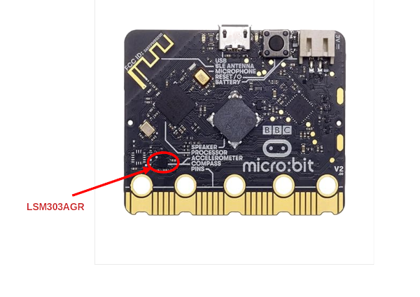
The sensor measures acceleration along three axes: X, Y, and Z. That lets us know how the board is moving or rotating in space.
You can find more technical details and the datasheet for the LSM303AGR chip in the official documentation here.
How Does an Accelerometer Work?
An accelerometer is a tiny sensor that can measure acceleration - the rate at which something speeds up, slows down, or changes direction. But how does it actually do that?
Think of It Like a Magic Marble
Imagine a tiny marble inside a box. When you tilt or shake the box, the marble rolls around. If the marble pushes against the left side, it means the box is moving right. If it presses the bottom, the box is moving upward.
An accelerometer works in a similar way. Inside the chip, there are tiny parts (called MEMS - Micro-Electro-Mechanical Systems) that move slightly when the device is shaken, tilted, or moved. These movements are so small that we can't see them, but special circuits detect how much and in which direction they moved.
Three Axes: X, Y, and Z
The accelerometer measures movement in three directions: the X-axis detects motion left and right, the Y-axis measures movement forward and backward, and the Z-axis captures movement up and down.
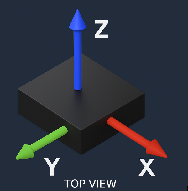
By looking at how much acceleration is happening on each axis, we can figure out if the device is standing still, moving, tilted, or even falling.
Accelerometer Axis on microbit
-
The X-axis runs horizontally across the board from button A to button B. It becomes positive when the board is moved or tilted to the right.
-
The Y-axis runs vertically from the USB connector to the gold edge connector (the golden lines marked with pin numbers like 0, 1, 3V, and GND). It becomes positive when the board is tilted downward toward the USB connector.
-
The Z-axis is perpendicular to the board. It is positive when the board is positioned face down (with the LED matrix facing the table) and negative when the board is lying flat with the LED matrix facing up.
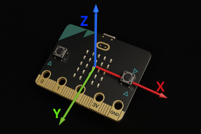
At rest on a flat surface, the micro:bit typically shows approximately +1g on the Z-axis due to gravity, while X and Y remain close to 0g.
Reference
- If you want in-depth understanding of how does accelerometer works, refer this video.
- How Accelerometers Work - The Learning Circuit: This is also another useful video that gives intro acceleration and accelerometer
How to Communicate with the LSM303AGR Accelerometer on micro:bit v2
We learned that the micro:bit v2 has a chip called LSM303AGR for the accelerometer (and magnetometer). But how does the nRF52 processor on the micro:bit actually talk to this chip?
To communicate with the sensor, we'll use a protocol called I2C. Since we haven't covered I2C yet, let's briefly look at what it is. We won't go into too much detail; just enough to understand what we need for this exercise.
I2C (Inter-Integrated Circuit) Serial Bus
I2C (pronounced "I-squared-C", also written as I²C or IIC) is a simple two-wire communication protocol that allows a microcontroller to exchange data with external devices like sensors, displays, and memory chips.
Think of I2C like a chat system between devices using just two wires.
The Two Wires:
- SDA (Serial Data Line) : This is the wire where the actual data travels. It's used to send and receive messages between the nRF52 processor and the sensor.
- SCL (Serial Clock Line) : This is like a traffic light. It tells the devices when it's their turn to speak. Just like cars at an intersection wait for the green light, the devices wait for the clock signal to send or receive data.

Who Talks First? Understanding Controller and Device Roles
In I2C communication, one device is in charge of starting and controlling the communication. The others respond when asked. Traditionally, these roles were called master and slave, but there are other alternative terms now used:
-
Controller (was "master"): the device that starts communication and controls the timing. In our case, this is the micro:bit's nRF52 chip.
-
Peripheral or Device (was "slave"): the chip that listens and responds to the controller. In our case, it is the LSM303AGR sensor.
You can think of the controller as the person asking questions, and the device as the person answering.
I2C Addresses: How the Controller Knows Who to Talk To
Each device on the I2C bus has a unique address; just like a house on a street has its own number. This is how the controller knows which device it's talking to.
Before sending any data, the controller first sends the device's address. Only the device with that address will respond. All the others stay quiet.
As stated in the LSM303AGR datasheet, The accelerometer sensor slave address is 0011001b while magnetic sensor slave address is 0011110b.
Example:
- The LSM303AGR accelerometer's address is 0x19 (in binary: 0011001).
- The magnetometer part has address 0x1E (in binary: 0011110).
So even though both are inside the same chip, the nRF52 can talk to each one separately by using the correct address.
I2C Bus on Microbit v2
The micro:bit v2 separates the I2C bus into two parts: internal and external. The internal I2C is used for communication between the nRF52833 processor and onboard components like the motion sensor and interface chip. The external I2C is routed to the edge connector(If you are wondering what is edge connector, refer the hardware details section) for connecting external accessories.
- The internal I2C uses GPIO pin P0.16 on the nRF52833 for SCL (
I2C_INT_SCL) and P0.08 for SDA (I2C_INT_SDA). - The external I2C uses GPIO pin P0.26 on the nRF52833 for SCL (
I2C_EXT_SCL, edge connector pin P19) and P1.00 for SDA (I2C_EXT_SDA, edge connector pin P20).
Since the accelerometer is an internal chip, it communicates over the internal I2C bus.
We will be using the "microbit-bsp" crate. In that crate, we can access the internal SDA and SCL lines like this:
#![allow(unused)]
fn main() {
let sda = board.i2c_int_sda;
let scl = board.i2c_int_scl;
}
Simple Rust Program to Read Values from the Accelerometer
Let's start by writing a simple Rust program that reads and prints values from the accelerometer. We will display the acceleration along the X, Y, and Z axes, expressed in milligravity (mg) units. We will be print the readings to the system console.
In later chapters, we will explore some fun exercises using these values. For now, let's get started!
Create Project from template
For this project, we will be using microbit-bsp (with Embassy). To generate a new project using the template, run the following command:
cargo generate --git https://github.com/ImplFerris/mb2-template.git --rev 3d07b56
-
When it prompts for a project name, type something like "accelerometer-print".
-
When it prompts whether to use async, select "true".
-
When it prompts you to select between "BSP" or "HAL", select the option "BSP".
Update Cargo.toml
The "lsm303agr" crate is a new dependency we are introducing. It is a platform-agnostic Rust driver for the LSM303AGR sensor, providing a convenient set of functions to read data from the device. We have enabled the "async" feature also for the driver.
lsm303agr = { version = "1.1.0", features = ["async"] }
static_cell = { version = "2" }
We also add the static_cell crate, which provides tools for safely creating and accessing static memory. We use it to allocate a fixed-size RAM buffer required by the TWIM (I2C) driver. This buffer must have a 'static lifetime and live in RAM, which static_cell helps manage safely.
Update the imports
Before we get started, let's update the imports needed for the I2C peripheral, timing, and the LSM303AGR sensor driver:
#![allow(unused)]
fn main() {
use defmt_rtt as _;
use embassy_executor::Spawner;
use embassy_time::{Delay, Duration, Timer};

// for I2C
use embassy_nrf::{self as hal, twim::Twim};
use hal::twim;

// LSM303AGR Driver
use lsm303agr::{AccelMode, AccelOutputDataRate, Lsm303agr};

// BSP Crate
use microbit_bsp::Microbit;
}
Initialize the Board
As usual, start by clearing out any existing lines inside the main function that come with the template. Then, add the following line to initialize the board:
#![allow(unused)]
fn main() {
let board = Microbit::default();
}
I2C Interrupt
We previously discussed interrupts in the Temperature Sensor chapter, so by now, you should have a basic understanding of how they work. For I2C communication, we need to enable the interrupt associated with the TWISPI0 peripheral.
TWISPI0 is a shared hardware peripheral on the nRF52833 that can function as either an I2C (TWI) or SPI interface, depending on how it's configured.
To do this, we use the bind_interrupts! macro from the embassy-nrf crate. This macro defines a unit struct named "Irqs" and connects the TWISPI0 interrupt to the appropriate handler. The macro also implements the required Binding trait for Irqs, which ensures a compile-time type check that the correct interrupt is configured. (If you are not sure what we are talking about here, refer to the Expanding bind_interrupts! Macro section.)
#![allow(unused)]
fn main() {
hal::bind_interrupts!(struct Irqs {
    TWISPI0 => twim::InterruptHandler<hal::peripherals::TWISPI0>;
});
}
Initialize sensor
Let's initialize the sensor. For this, we first create an I2C interface using the embassy-nrf and BSP crates. Once the I2C interface is instantiated, we pass it to the Lsm303agr driver to initialize the sensor.
Add the necessary imports:
#![allow(unused)]
fn main() {
use embassy_nrf::{self as hal, twim::Twim};
use hal::twim;
use lsm303agr::Lsm303agr;
}
Two Wire Interface in Master mode (TWIM)
We initialize the I2C-compatible TWIM driver provided by the embassy-nrf crate. This peripheral allows the nRF processor to act as an I2C master and communicate with devices like the LSM303AGR sensor.
We will create a Twim instance, which requires the I2C peripheral (TWISPI0), the interrupt handler (Irqs), the I2C pins (SDA and SCL), and configuration (which we will leave it to default).
#![allow(unused)]
fn main() {
static RAM_BUFFER: ConstStaticCell<[u8; 16]> = ConstStaticCell::new([0; 16]);
let twim_config = twim::Config::default();
let twim0 = Twim::new(
    board.twispi0,
    Irqs,
    board.i2c_int_sda, // Internal I2C SDA, GPIO Pin: P0_08
    board.i2c_int_scl, // Internal I2C SCL, GPIO Pin:P0_08
    twim_config,
    RAM_BUFFER.take(),
);
}
The last parameter is a RAM buffer that the TWIM driver uses when sending data. If the data is stored in flash memory (like fixed byte arrays written in your code), it cannot be sent directly over I2C. The driver first copies it into RAM using this buffer. We use ConstStaticCell to safely create the buffer in RAM, and .take() gives us safe access to it. A 16-byte buffer is usually enough for common I2C tasks like talking to sensors. If the RAM buffer is too small to hold the data being sent, the TWIM driver will panic and return a RAMBufferTooSmall error.
Lsm303agr Driver
Once the TWIM is initialized, we can pass it to the Lsm303agr::new_with_i2c function, which creates a new instance of the sensor driver using the provided I2C interface.
#![allow(unused)]
fn main() {
let mut sensor = Lsm303agr::new_with_i2c(twim0);
}
Embedded HAL Trait: Gluing embassy-nrf HAL with lsm303agr Driver
This is an optional section to understand how the embedded-hal trait helps to glue the HAL with the driver. We will just take a quick look at how Twim and Lsm303agr are connected through this trait system. You can skip this for now and come back to it later if you're interested.
Drivers like lsm303agr are made to work on many different boards, not just the micro:bit. They do this by using the embedded-hal traits, which define common interfaces like I2C. These traits don't depend on any specific microcontroller. The actual hardware support comes from HALs like embassy-nrf, which provide the real implementation for chips such as the nRF52833 used in the micro:bit v2.
In this section, we will see how these components fit together. Specifically, how the Twim instance from embassy-nrf can be passed to the lsm303agr driver, allowing it to talk to the LSM303AGR sensor using the embedded-hal traits.
The I2C trait defines functions:
- transaction: Performs a sequence of reads and writes as a single I2C transaction. This is the core method that must be implemented by the HAL. The other functions (read, write, write_read) are built on top of this.
- read: Reads bytes from the I2C slave. This has a default implementation that internally calls transaction.
- write: Writes bytes to the slave. This also has a default implementation that uses transaction.
- write_read: Writes a few bytes, then reads from the slave without releasing the bus. This too is implemented using transaction.
You can see the trait definition here
I2c Trait and HAL Integration
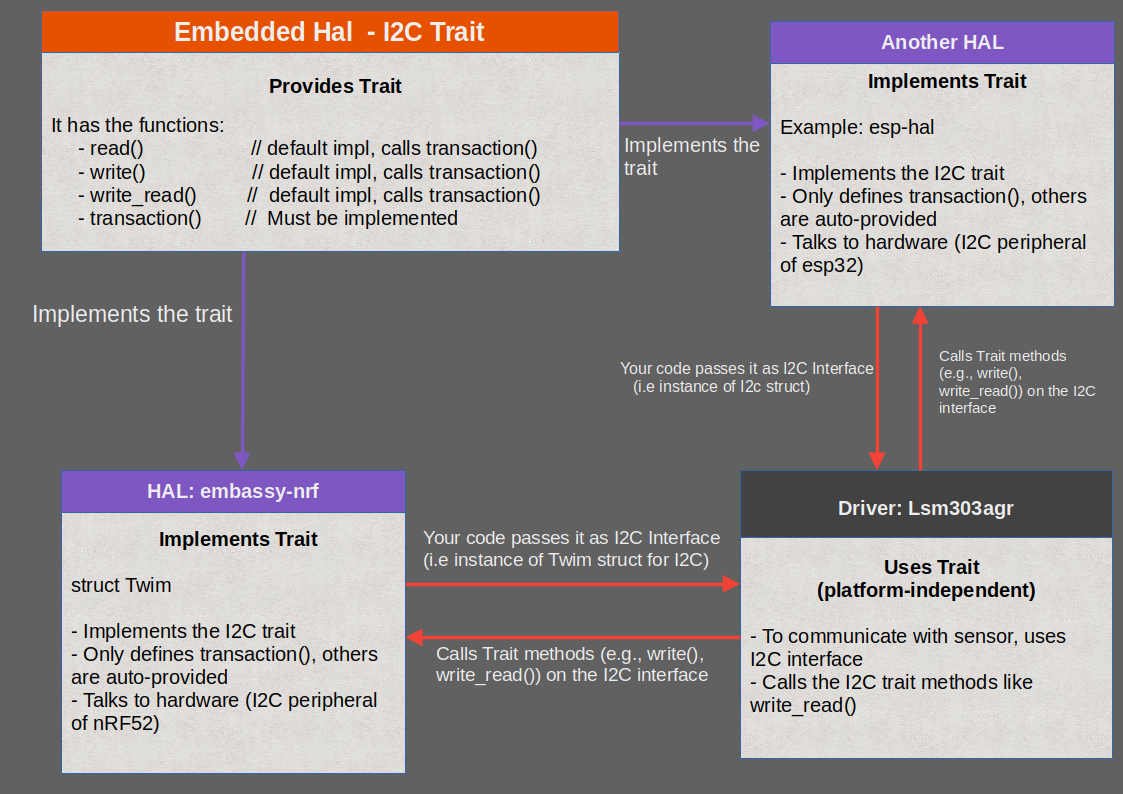
This is an example diagram illustrating one of the traits provided by embedded-hal, the I2c trait. As we learned, this trait defines four functions, and the transaction function must be implemented by the HAL.
The lsm303agr driver works with any I2C interface that implements the I2c trait. As shown in the diagram, multiple HALs can implement this trait. For example, the embassy-nrf HAL provides an implementation of I2c for the Twim struct, which can be used with lsm303agr.
Similarly, another HAL like esp-hal (for ESP32) also implements the I2c trait. This means we can use the same lsm303agr driver on different platforms just by passing in a compatible I2C implementation. This trait-based design makes the driver platform-independent and reusable across different boards like the ESP32 and nRF-based micro:bit.
Driver (lsm303agr) side
Now let's look at what happens on the driver side with an example. When you call "sensor.acceleration()", it eventually results in calling the "write_read" function of the I2c trait provided by the embedded-hal-async(since we are using the async version). Similarly, when you call sensor.init(), it results in calling the "write".
Here's a simplified version of the function used inside the lsm303agr crate to read the accelerometer:
#![allow(unused)]
fn main() {
// sensor.acceleration() calls => read_accel_3_double_registers() calls => i2c.write_read()
async fn read_3_double_registers<R: RegRead<(u16, u16, u16)>>(
        &mut self,
        address: u8,
    ) -> Result<R::Output, Error<E>> {
        let mut data = [0; 6];

    // Here, the driver uses the I2C interface we provided and calls its "write_read" function
    self.i2c
        .write_read(address, &[R::ADDR | 0x80], &mut data)
        .await
        .map_err(Error::Comm)?;

    Ok(R::from_data((
        u16::from_le_bytes([data[0], data[1]]),
        u16::from_le_bytes([data[2], data[3]]),
        u16::from_le_bytes([data[4], data[5]]),
    )))
}
}
This function is defined in the lsm303agr crate and uses "write_read" on the provided I2C interface. In our case, that I2C interface is an instance of Twim struct from embassy-nrf.
HAL (embassy-nrf) side
Here is how the Twim struct implements the I2c trait (you can also find this in the Github repository):
#![allow(unused)]
fn main() {
// Trait implementation
impl<'d, T: Instance> embedded_hal_async::i2c::I2c for Twim<'d, T> {
    async fn transaction(&mut self, address: u8, operations: &mut [Operation<'_>]) -> Result<(), Self::Error> {
        self.transaction(address, operations).await
    }
}

// ...
// ...
impl<'d, T: Instance> Twim<'d, T> {
    ...
    pub async fn transaction(&mut self, address: u8, mut operations: &mut [Operation<'_>]) -> Result<(), Error> {
        // The full logic of the function, which is not important for us at the moment.
        Ok(())
    }
// ...
}
}
Now, you might wonder: if the Twim type implements the embedded_hal_async::i2c::I2c trait, where are the rest of the required functions like write_read, read, or write defined?
The answer is: they are not defined manually in the Twim implementation. And they don't have to be.
That's because the embedded-hal-async crate provides default implementations of these methods (read, write, and write_read) using just the transaction function.
This means that once Twim implements the transaction method, all the other required methods automatically become available through the trait's default implementation.
For example, here is the default implementation of the write function:
#![allow(unused)]
fn main() {
 #[inline]
    async fn write(&mut self, address: A, write: &[u8]) -> Result<(), Self::Error> {
        self.transaction(address, &mut [Operation::Write(write)]) // => Calls the transaction
            .await
    }
}
This design pattern is what makes embedded Rust so powerful and modular. HAL crates only need to implement minimal logic, and driver crates stay reusable across different platforms.
Printing Accelerometer values
We will call the "init" function on the sensor instance. This will initialize the register and prepare the accelerometer for the reading.
#![allow(unused)]
fn main() {
sensor.init().await.unwrap();
}
Configuring Operating Mode and Output Data Rate (ODR)
Next, we will configure the accelerometer's operating mode and output data rate (ODR).
As described in the datasheet (page 27), the LSM303AGR supports three accelerometer operating modes: high-resolution mode, normal mode, and low-power mode.
High-resolution mode provides the finest measurement precision with a resolution of 12 bits. This mode is highly sensitive to small changes in motion or tilt, making it suitable for applications where accuracy is important. However, this increased precision comes with higher power consumption compared to the other modes.
The output data rate (ODR) determines how frequently the sensor provides new acceleration data. Setting the ODR to 50 Hz means the sensor updates its readings 50 times per second. This rate is responsive enough for most human-scale activities like walking, tilting, or detecting gestures, while keeping power consumption relatively low.
#![allow(unused)]
fn main() {
 sensor
    .set_accel_mode_and_odr(
        &mut Delay,
        AccelMode::HighResolution,
        AccelOutputDataRate::Hz50,
    )
    .await
    .unwrap();
}
At a 50 Hz output data rate, the turn-on time is approximately 7 ms, and the current consumption in high-resolution mode is about 12.6 µA. Choosing high-resolution mode with a 50 Hz ODR offers a well-balanced trade-off between accuracy and energy efficiency. It allows the system to capture detailed motion information without overwhelming the processor or draining the battery quickly.
Read values
Inside a loop, we will check if a new accelerometer reading is available using the snippet sensor.accel_status().await.unwrap().xyz_new_data().
The "accel_status" function reads the status register of the accelerometer, and the "xyz_new_data" function checks a specific flag within that register to determine whether new data is available for all three axes: X, Y, and Z.
If new data is available, we use the "acceleration" function to get the latest X, Y, and Z values. These values are then converted from raw sensor data into milligravity (mg).
The full code
Here is the complete code that puts everything together:
#![no_std]
#![no_main]

use embassy_nrf::{self as hal, twim::Twim};
use hal::twim;

use defmt_rtt as _;
use embassy_executor::Spawner;
use embassy_time::{Delay, Timer};
use lsm303agr::{AccelMode, AccelOutputDataRate, Lsm303agr};
use microbit_bsp::Microbit;
use static_cell::ConstStaticCell;
use {defmt_rtt as _, panic_probe as _};

hal::bind_interrupts!(struct Irqs {
    TWISPI0 => twim::InterruptHandler<hal::peripherals::TWISPI0>;
});

#[embassy_executor::main]
async fn main(_spawner: Spawner) -> ! {
    let board = Microbit::default();

    let twim_config = twim::Config::default();
    static RAM_BUFFER: ConstStaticCell<[u8; 16]> = ConstStaticCell::new([0; 16]);

    let twim0 = Twim::new(
        board.twispi0,
        Irqs,
        board.i2c_int_sda,
        board.i2c_int_scl,
        twim_config,
        RAM_BUFFER.take(),
    );

    let mut sensor = Lsm303agr::new_with_i2c(twim0);
    sensor.init().await.unwrap();
    sensor
        .set_accel_mode_and_odr(
            &mut Delay,
            AccelMode::HighResolution,
            AccelOutputDataRate::Hz50,
        )
        .await
        .unwrap();

    loop {
        if sensor.accel_status().await.unwrap().xyz_new_data() {
            let data = sensor.acceleration().await.unwrap();
            // milli-g values
            let x = data.x_mg();
            let y = data.y_mg();
            let z = data.z_mg();
            defmt::info!("x:{}, y:{}, z:{}", x, y, z);
        }
        Timer::after_secs(1).await;
    }
}
Clone the existing project
You can also clone (or refer) project I created and navigate to the bsp-embassy/accelerometer-print folder.
git clone https://github.com/ImplFerris/microbit-projects
cd microbit-projects/bsp-embassy/accelerometer-print
Run
You can flash the program into the micro:bit and should see the readings getting printed on your computer
cargo run
Try changing the orientation of the board, shaking it, or tilting it in different directions. You will see the X, Y, and Z values change based on how the board moves.
Observations
Let's see the accelerometer values with the micro:bit in different positions.
X Positive Close to 1g
When you place the micro:bit so that the golden logo is on the right side (as shown in the picture), the X-axis reading will be close to +1000 mg. The Y and Z values will be close to zero.
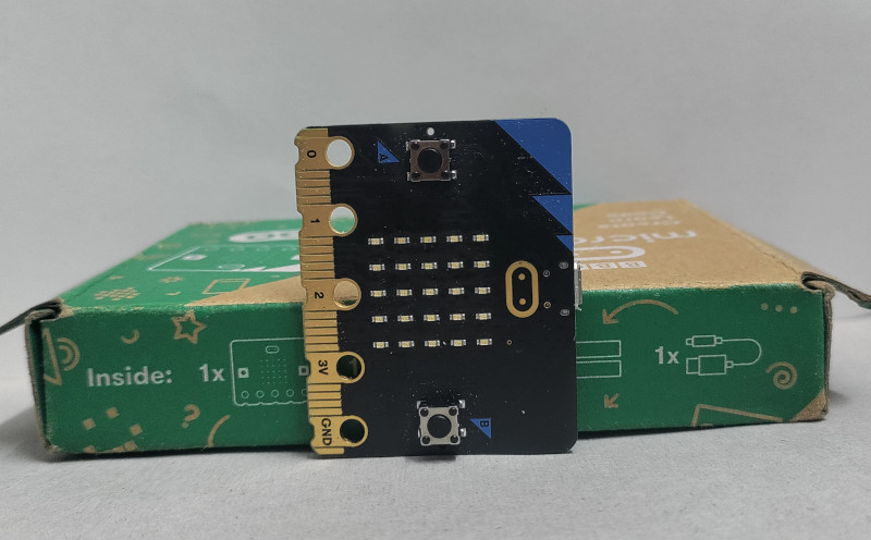
X Negative Close to 1g
When you place the micro:bit so that the golden logo is on the left side (as shown in the picture), the X-axis reading will be close to -1000 mg. The Y and Z values will be close to zero.
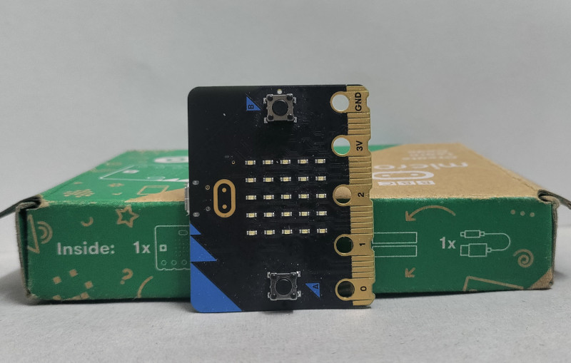
Y Positive Close to 1g
When you position the micro:bit so that the USB connector points downward (as shown in the picture), the Y-axis reading will be close to +1000 mg. The X and Z values will be close to zero.
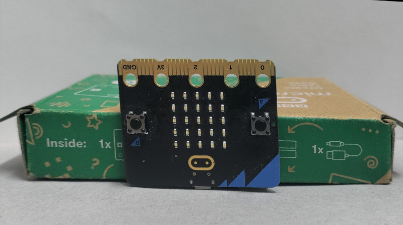
Y Negative Close to 1g
When you position the micro:bit so that the edge connector points downward (as shown in the picture), the Y-axis reading will be close to -1000 mg. The X and Z values will be close to zero.
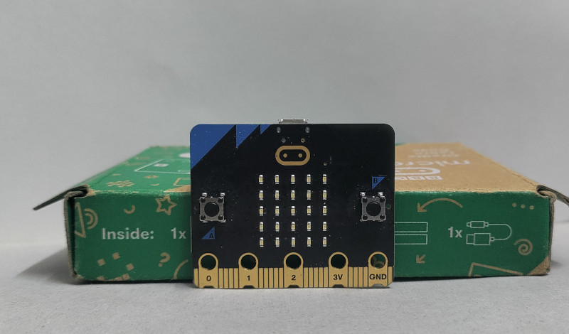
Z Positive Close to 1g
When you place the micro:bit face down (LED matrix facing down), the Z-axis reading will be close to +1000 mg. The X and Y values will be close to zero.
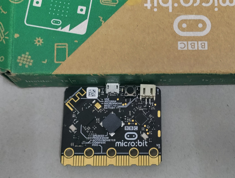
Z Negative Close to 1g
When you place the micro:bit face up (LED matrix facing up), the Z-axis reading will be close to -1000 mg. The X and Y values will be close to zero.
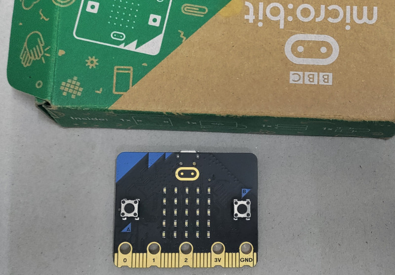
Other Position
Hold the micro:bit in your hand and slowly tilt it in different directions. Observe how the X, Y, and Z values change as you rotate the board.
Gravity
From our observation, if we keep the Micro:bit resting on a table with the chip side (opposite to the LED matrix) facing up, it gives a Z value around +1000. But wait, the definition of acceleration is the rate of change of velocity with respect to time. So if the Micro:bit isn't moving, why are we getting a non-zero value?
Because, Gravity!
1 g (1000 mg), which represents the standard acceleration due to gravity on Earth, is approximately 9.8 m/s². And that's exactly what the accelerometer is reacting to.
Why positive when chip side is facing up?
If you're wondering what it really means when the Z value is positive with the chip side facing up and negative when the LED matrix side is up ; you're on the same boat as me. It puzzled me too. I ignored it at first, but it kept bothering me. So I finally dug into it again and came across a great article from Movella that cleared up the confusion.
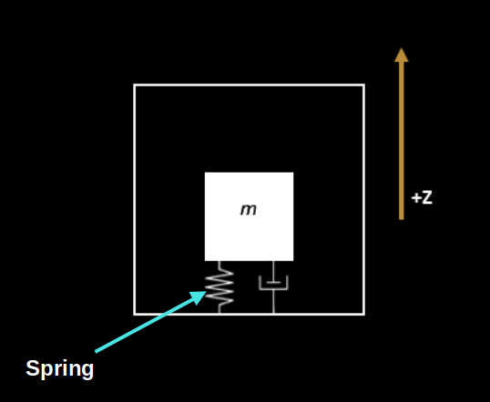
Simplified, single-axis MEMS accelerometer - image derived from: Movella
As we know, the sensor chip is mounted on the back side of the Micro:bit (opposite the LED matrix). Imagine the accelerometer positioned like in the image above, with the chip side facing up. The black box marked m is the mass (technically called the "proof mass"). The part that looks like a spring is indeed a spring, not to be confused as a resistor.
How the Sensor Reacts to Gravity and Movement
The fundamental principle behind a MEMS accelerometer is that a tiny mass is suspended inside the chip by springs. When acceleration happens, the mass wants to stay where it is (thanks to inertia), and the springs either compress or stretch depending on the direction of the acceleration.
Now, gravity is always pulling down; towards the Earth's center. So when the Micro:bit is resting on the table with the chip side facing up, gravity pulls the internal mass downward. This compresses the spring, and like any spring you've played with, it wants to push back to its original shape. That push-back force is upward ; in the positive Z direction. And that's what the sensor measures as +1 g.
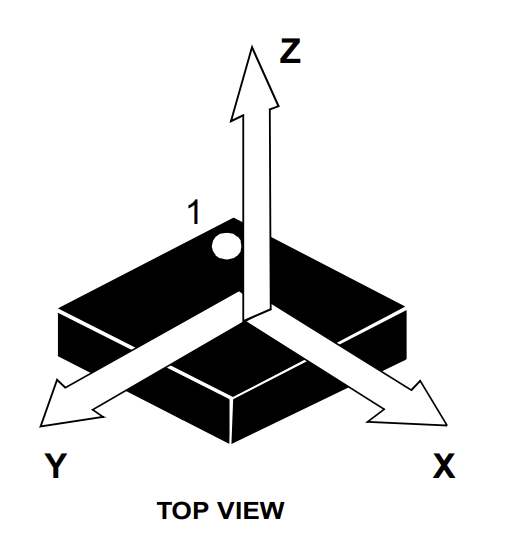
Image source: lsm303agr Datasheet
If the accelerometer is accelerated upward (along the positive Z-axis), the internal mass tends to stay in place due to inertia. This also causes the spring to compress, creating upward force. The sensor interprets this increased force as a positive acceleration along the Z axis.
Likewise, if the accelerometer is accelerated downwards (along the negative Z-axis), then the internal proof mass will pull upwards, elongating the spring-damper system. The accelerometer will sense this as a negative acceleration.
If you flip the Micro:bit so the LED matrix is facing up, the Z axis now points downward. Gravity still pulls the mass down, but since the Z axis has flipped, that pull is now in the negative Z direction. This causes the spring to stretch, because the mass is still resisting the pull. The spring pulls downward (in the -Z direction), and that's why the sensor reads around -1000.
Writing Shake Detection Code with microbit in Rust
We have successfully printed the accelerometer readings to the system console. We assume you have tried tilting the microbit in different directions and noticed how the values change. While that is fun, simply printing values is not very exciting. In this chapter, we will write a program that plays a tone when you shake the micro:bit.
Create Project from template
For this project, we will be using microbit-bsp (with Embassy). To generate a new project using the template, run the following command:
cargo generate --git https://github.com/ImplFerris/mb2-template.git --rev 3d07b56
-
When it prompts for a project name, type something like "accelerometer-print".
-
When it prompts whether to use async, select "true".
-
When it prompts you to select between "BSP" or "HAL", select the option "BSP".
Update Cargo.toml
Open the Cargo.toml file and add the following lines:
lsm303agr = { version = "1.1.0", features = ["async"] }
static_cell = { version = "2" }
How to detect shake?
To detect a shake, we first need to calculate the magnitude of the accelerometer readings. The formula for computing the magnitude is:
$$ \text{magnitude} = \sqrt{x^2 + y^2 + z^2} $$
Example Calculation
Let's take one sample reading and calculate its magnitude.
Sample value: x = 81, y = -105, z = -1018
#![allow(unused)]
fn main() {
x = 81          => x^2 = 6561
y = -105        => y^2 = 11025
z = -1018       => z^2 = 1036324

magnitude^2 = 6561 + 11025 + 1036324 = 1053910
magnitude   = sqrt(1053910) ≈ 1026.6
}
Let's take one more sample reading: x:-875, y:-567, z:-143
#![allow(unused)]
fn main() {
x^2          = (-875)^2   = 765625
y^2          = (-567)^2   = 321489
z^2          = (-143)^2   = 20449

magnitude^2  = 765625 + 321489 + 20449 = 1107563
magnitude    = sqrt(1107563) ≈ 1052.4
}
Readings While Shaking the Microbit
You can try a few more sample readings and calculate their magnitudes. Most values at rest should be close to 1000. Now, run the previous program to print accelerometer values. This time, shake the micro:bit well and observe the readings.
Here is one sample I recorded while shaking the device: x:-1265, y:-2029, z:1657
#![allow(unused)]
fn main() {
x^2          = (-1265)^2  = 1600225
y^2          = (-2029)^2  = 4116841
z^2          = (1657)^2   = 2745649

magnitude^2  = 1600225 + 4116841 + 2745649 = 8462715
magnitude    = sqrt(8462715) ≈ 2909.07
}
Woah, now the magnitude is nearly 3000! This is a significant jump from the resting value and clearly indicates a strong shake.
To detect a shake in code, we can choose a threshold value (for example, 2000) and compare the calculated magnitude against it. If the magnitude is greater than this threshold, we can say a shake has occurred.
How to calculate Square Root(sqrt) in Embedded Rust (#![no_std])
The sqrt() function is not available in a no_std environment by default. While crates like "libm" provide math functions for no_std, we will use a simpler and more efficient approach.
Instead of calculating the square root, we can square the threshold and compare it directly with the squared magnitude. For example, if our threshold is 2000, we square it to get 4,000,000. Then we compare the squared magnitude against this value.
#![allow(unused)]
fn main() {
// Instead of this:
2909.07 > 2000

// We do this:
8462715 > 4000000
}
Code to detect Shake
Let's convert the threshold comparison logic into Rust code. Below is a function that takes x, y, and z accelerometer readings and returns true if a shake is detected.
#![allow(unused)]
fn main() {
const SHAKE_THRESHOLD_MG: i32 = 2000;
const SHAKE_THRESHOLD_SQUARED: i64 = (SHAKE_THRESHOLD_MG * SHAKE_THRESHOLD_MG) as i64;

fn detect_shake(x: i32, y: i32, z: i32) -> bool {
    let mag_sq = x as i64 * x as i64 + y as i64 * y as i64 + z as i64 * z as i64;
    mag_sq > SHAKE_THRESHOLD_SQUARED
}
}
The Full code
You may need to adjust the threshold value and delay timing depending on how you shake the device and the level of sensitivity you want to achieve.
#![no_std]
#![no_main]

use defmt::info;
use embassy_nrf::{self as hal, pwm::SimplePwm, twim::Twim};
use hal::twim;

use defmt_rtt as _;
use embassy_executor::Spawner;
use embassy_time::{Delay, Timer};
use lsm303agr::{AccelMode, AccelOutputDataRate, Lsm303agr};
use microbit_bsp::{
    Microbit,
    speaker::{NamedPitch, Pitch, PwmSpeaker},
};
use static_cell::ConstStaticCell;

#[panic_handler]
fn panic(panic_info: &core::panic::PanicInfo) -> ! {
    info!("{:?}", panic_info);
    loop {}
}

hal::bind_interrupts!(struct Irqs {
    TWISPI0 => twim::InterruptHandler<hal::peripherals::TWISPI0>;
});

const SHAKE_THRESHOLD_MG: i32 = 2000;

const SHAKE_THRESHOLD_SQUARED: i64 = (SHAKE_THRESHOLD_MG * SHAKE_THRESHOLD_MG) as i64;

fn detect_shake(x: i32, y: i32, z: i32) -> bool {
    let mag_sq = x as i64 * x as i64 + y as i64 * y as i64 + z as i64 * z as i64;
    mag_sq > SHAKE_THRESHOLD_SQUARED
}

#[embassy_executor::main]
async fn main(_spawner: Spawner) -> ! {
    // let p = embassy_nrf::init(Default::default());
    let board = Microbit::default();

    static RAM_BUFFER: ConstStaticCell<[u8; 16]> = ConstStaticCell::new([0; 16]);
    let twim_config = twim::Config::default();
    let twim0 = Twim::new(
        board.twispi0,
        Irqs,
        board.i2c_int_sda,
        board.i2c_int_scl,
        twim_config,
        RAM_BUFFER.take(),
    );

    let mut speaker = PwmSpeaker::new(SimplePwm::new_1ch(board.pwm0, board.speaker));

    let mut sensor = Lsm303agr::new_with_i2c(twim0);
    sensor.init().await.unwrap();
    sensor
        .set_accel_mode_and_odr(
            &mut Delay,
            AccelMode::HighResolution,
            AccelOutputDataRate::Hz50,
        )
        .await
        .unwrap();

    loop {
        if sensor.accel_status().await.unwrap().xyz_new_data() {
            let data = sensor.acceleration().await.unwrap();
            let x = data.x_mg();
            let y = data.y_mg();
            let z = data.z_mg();
            if detect_shake(x, y, z) {
                // info!("SHAKE => x:{}, y:{}, z:{}", x, y, z);
                speaker.start_note(Pitch::Named(NamedPitch::A4));
                Timer::after_millis(100).await;
                speaker.stop();
            }
        }
        Timer::after_millis(50).await;
    }
}
Clone the Quick start project
You can clone the quick start project I created and navigate to the project folder and run it.
git clone https://github.com/ImplFerris/microbit-projects
cd microbit-projects/bsp-embassy/shake-detect
Flash - Run Rust Run
All that's left is to flash the code to your micro:bit and see it in action.
Run the following command from your project folder:
#![allow(unused)]
fn main() {
cargo run
}
Now, try to shake the microbit, it should play a tone when a shake is detected.
Applications
What else can you do with shake detection? Plenty of fun and creative possibilities!
Here are a few ideas:
-
Shake to roll a dice: Each shake generates a random number between 1 and 6.
-
Shake to change color or animation: Update an LED pattern or display a new frame each time the micro:bit is shaken.
-
Shake to control a game: Use shakes as input for jumping, moving, or triggering actions in simple games.
-
Step counter: Detect small, repeated shakes to count steps like a basic pedometer.
Bluetooth
Bluetooth needs no introduction. You probably use it daily; connecting your wireless headphones with your phone, wireless mouse, smartwatch, and more. In smart homes, Bluetooth helps link different devices. For example, you can control lights, appliances, and thermostats using Bluetooth-enabled apps on your phone.
Bluetooth was named after King Harald "Bluetooth" Gormsson. During a meeting, Jim Kardach from Intel suggested it as a temporary code name. Kardach later said, "King Harald Bluetooth…was famous for uniting Scandinavia just as we intended to unite the PC and cellular industries with a short-range wireless link"
Categories
Bluetooth technology is divided into two main types: Bluetooth Classic and Bluetooth Low Energy (BLE).
Bluetooth Classic
Bluetooth Classic is the original version of Bluetooth, commonly used in devices that require continuous data transfer, such as wireless headsets, speakers, and mouse. Before BLE was introduced, it was simply called "Bluetooth," but now it's referred to as Bluetooth Classic to distinguish it from BLE. It offers higher data rates, making it ideal for real-time applications like audio streaming.
Bluetooth Low Energy (BLE)
BLE is designed for low power consumption, making it great for devices that send small amounts of data from time to time. This is especially useful for battery-powered IoT devices, such as fitness trackers and environmental sensors. Compared to Classic, BLE has lower latency, meaning it takes less time to start sending or receiving data after a connection is made.
Dual Mode
Many modern devices support both Bluetooth Classic and BLE, a feature known as "Dual Mode." For example, a smartphone might use Classic for streaming music and BLE to connect to a smartwatch.
In general, Bluetooth Classic is better suited for continuous data transmission, such as real-time audio and video, while BLE is ideal for low-power communication with health monitors, sensors, and other small gadgets.
Microbit Bluetooth
The micro:bit supports Bluetooth 5.1 using Bluetooth Low Energy (BLE) via the Nordic S113 SoftDevice. While it doesn't support Bluetooth Classic, its BLE capabilities are enough for many practical applications, such as sending sensor data to a phone, controlling LEDs from an app, or communicating with other micro:bits.
⚠️ Heads up: This might be one of the more challenging chapters in this book. Working with Bluetooth Low Energy (BLE) is not simple. There are many things to learn and understand. Before we can run our Rust program, we need to flash the SoftDevice (a special Bluetooth firmware) onto the micro:bit. We also need to update the memory.x file to make sure our program doesn't overwrite the space used by the SoftDevice.
BLE
To work with Bluetooth Low Energy, we need to understand several key concepts. I'll keep it simple and cover just enough to get you started without overwhelming you with too many details. So, buckle up, and let's jump in.
BLE Stack
The image below illustrates the Bluetooth Low Energy (BLE) protocol stack. The BLE stack is the foundation of communication between BLE devices. We won't go into the Controller (lower layers) in detail, as it's not essential for our purpose. However, understanding key concepts in the Host part, such as GAP and GATT, is important.
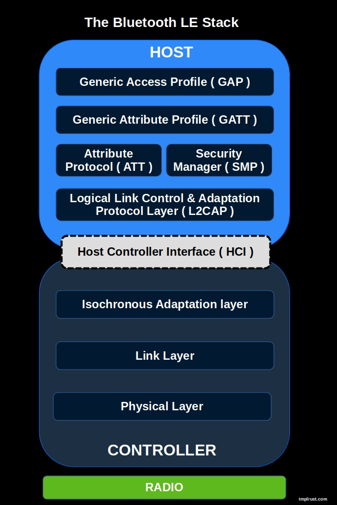
GAP => How devices connect and communicate
GAP (Generic Access Profile) defines how BLE devices advertise, connect, and establish communication. It covers device roles (e.g., central, peripheral), connection parameters, and security modes. GAP is responsible for how devices find each other and initiate communication.
GATT => How devices exchange and structure data
GATT (Generic Attribute Profile) defines how BLE devices exchange data. It organizes data in a hierarchy of services and characteristics, allowing clients (e.g., a smartphone app) to read, write, and subscribe to updates from a BLE peripheral (e.g., a sensor).
References
If you want deeper understanding, you can refer the following resources
Generic Access Profile (GAP)
GAP (Generic Access Profile) is a set of rules that control how Bluetooth Low Energy (BLE) devices discover, connect, and communicate with each other.
BLE Communication Types
BLE supports two main ways to communicate: connected communication and broadcast communication.
Connected Communication : Two devices form a direct connection, allowing them to send and receive data both ways. For example, a smartwatch connects to a phone and continuously shares data like heart rate, notifications, and step count.
Broadcast Communication: A device sends data to all nearby devices without making a direct connection. For example, a Bluetooth beacon in a store broadcasts promotional messages to all phones in range.
Device Roles
Imagine these roles like in real-world human communication. Just as people interact in different ways depending on their roles in a conversation, Bluetooth Low Energy (BLE) devices have specific roles.
📢 Broadcaster (connection-less): Sends out information (advertisements) but cannot be connected to.
For example, a beacon in a shopping mall continuously sends discount offers to nearby smartphones. The phones can receive the offers but cannot connect to the beacon.
📡 Observer (connection-less): Listens for Bluetooth advertisements but cannot connect to other devices.
For example, a smartphone app scans for beacons to detect nearby stores but does not connect to them.
📱 Central (connection-oriented): This device searches for other devices, connects to them, or reads their advertisement data. It usually has more processing power and resources. It can handle multiple connections at the same time.
For example, a smartphone connects to a smartwatch, a fitness tracker, and wireless earbuds simultaneously.
⌚ Peripheral (connection-oriented): This device broadcasts advertisements and accepts connection requests from central devices. For example, a fitness tracker advertises itself so a smartphone can find and connect to it for syncing health data.
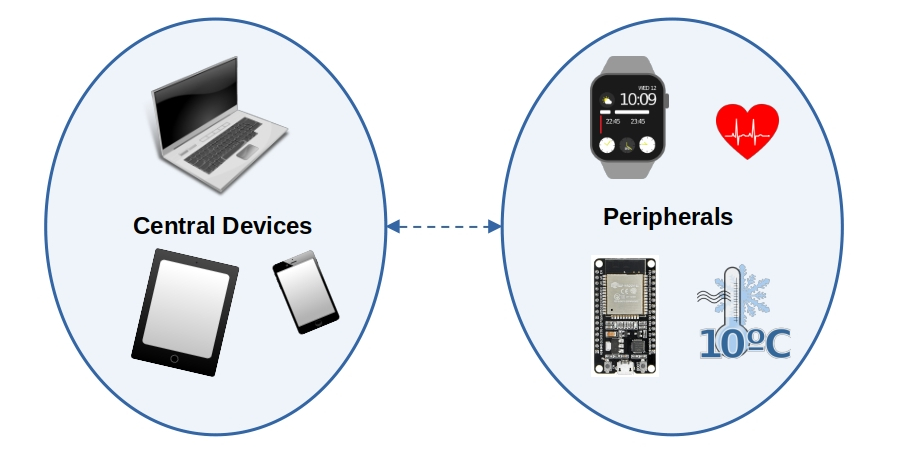
BLE Peripheral Discovery Modes & Advertisement Flags
A BLE peripheral can be in different discovery modes, affecting how it is detected by central devices. These modes are set using advertisement flags in the advertising packet.
Discovery Modes
-
Non-Discoverable
- Default mode when no advertising is active or when a connection is established.
- Cannot be discovered or connected to.
-
Limited-Discoverable
- Discoverable for a limited time to save power.
- If no connection is made, the device goes idle.
-
General-Discoverable
- Advertises indefinitely until a connection is established.
Advertisement Flags
These flags indicate the discovery mode and BLE support level. They are combined using bitwise OR (|):
| Bit | Description |
|---|---|
| 0 | Limited discoverable mode (temporary advertising). |
| 1 | General discoverable mode (advertises indefinitely). |
| 2 | Set when the device does not support (or doesn't want to) Bluetooth Classic (BR/EDR). |
| 3 | Set if the device can use both Bluetooth Low Energy (LE) and Classic Bluetooth at the same time (Controller level). |
| 4 | Set if the device can run both Bluetooth Low Energy (LE) and Classic Bluetooth at the same time (Host level). |
| 5-7 | Reserved |
We will use the softdevice crate later for Bluetooth. It provides a advertisement builder where we can pass advertisement flags.
For example, to configure the peripheral to advertise indefinitely and indicate that it does not support Bluetooth Classic:
#![allow(unused)]
fn main() {
LegacyAdvertisementBuilder::new()
    .flags(&[
         Flag::GeneralDiscovery,    // 0b0000_0010     (Sets bit 1)
         Flag::LE_Only,             // 0b0000_0100    (Sets bit 2)
   ])
}
Directed vs Undirected Advertising
Indicates whether the advertisement is meant for a specific central device or any nearby device.
-
Undirected: Sent to any nearby central or observer. Used when the peripheral is open to connections from any device.
-
Directed: Sent to one specific central, identified by its Bluetooth address. Only that device is allowed to respond.
Connectable vs Non-Connectable Advertising
This tells whether a central device is allowed to initiate a connection with the peripheral.
-
Connectable: The central can send a connection request to the peripheral.
-
Non-Connectable: The peripheral only sends advertisements; it will not accept any connection requests.
Scannable vs Non-Scannable Advertising
Defines whether a central can request extra information from the peripheral via scan request.
-
Scannable: The peripheral accepts scan requests and responds with extra information (scan response).
-
Non-Scannable: The peripheral does not respond to scan requests.
Example
In the nrf-softdevice crate, to make your device connectable, scannable, and undirected (i.e. visible to any central nearby), you would write:
#![allow(unused)]
fn main() {
peripheral::ConnectableAdvertisement::ScannableUndirected {
   adv_data: &ADV_DATA,
   scan_data: &SCAN_DATA,
}
}
This tells the SoftDevice to accept connection requests from any central device, respond to scan requests with additional data, and advertise to all nearby devices without targeting a specific one.
Attribute Protocol (ATT) and Generic Attribute Profile (GATT)
In the previous chapter, we learned that the GAP layer helps Bluetooth LE devices find each other through advertising. After they connect, they need a way to send and receive data. This is where the ATT and GATT layers come in; they define how data is structured and transmitted between devices.
Client-Server Model
There are two roles in GATT: Server and Client. The server holds data as attributes, and the client accesses this data. Typically, a peripheral device (like a sensor) acts as the server, and a central device (such as a smartphone) functions as the client.
The client and server roles in GATT are independent of the peripheral and central roles in the GAP. This means a central device can be either a client or a server, and the same applies to a peripheral device.
For example, in a smartphone and fitness tracker scenario, the fitness tracker (peripheral) typically acts as a GATT server, storing sensor data like heart rate or step count, while the smartphone (central) acts as a GATT client, reading this data to display it in an app.
However, if the smartphone needs to send configuration settings to the tracker (e.g., adjusting display brightness or setting an alarm), it temporarily becomes the server, and the fitness tracker acts as the client to receive these settings.
Attribute Protocol (ATT) - The Foundation
ATT defines how data is stored as attributes; attributes are the base foundation and building blocks. Each attribute has a unique handle, type(a 16-bit identifier or 128-bit UUID), permissions (e.g., readable, writable), and data(the actual value). The client can read, write, or subscribe to data.
Generic Attribute Profile (GATT) - Organizing the Data
GATT builds on ATT by adding structure and meaning to the data. It defines how data is grouped and accessed.
GATT organizes attributes into:
-
Characteristic: a single piece of data that a device can share. Other devices can read, write, or receive updates from it. For example, a Heart Rate Measurement characteristic holds the current heart rate and can send updates when it changes.
-
Service: a collection of related characteristics grouped together. For example, the Heart Rate Service includes characteristics for heart rate measurement and the sensor's location on the body.
-
Profiles: A collection of related services (e.g., Heart Rate Service, Device Information Service).
The following picture illustrates the profile, services and characteristics for the Heart Rate Sensor
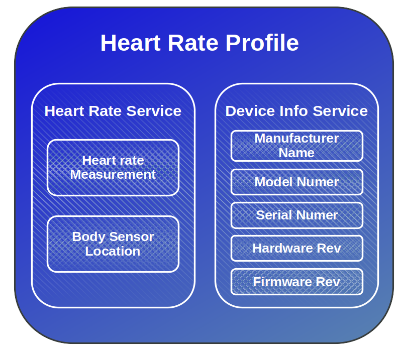
Characteristic Descriptors
Descriptors are optional attributes that provide extra information or control over how a characteristic behaves.
The most commonly used descriptor is the Client Characteristic Configuration Descriptor (CCCD). It allows a client (like a smartphone) to enable or disable notifications or indications from the server (like a heart rate sensor).
For example, in the Heart Rate Service, the client can write to the CCCD to subscribe to updates. This way, the heart rate sensor can push new data to the phone without the phone having to keep asking.
UUID
Let's revisit the UUID part in the attribute. Each service and characteristic should have a unique ID value. The UUID could be either a standard Bluetooth-SIG defined UUID (16-bit) or a custom UUID (128-bit).
You can get the predefined UUID list from here: https://www.bluetooth.com/specifications/assigned-numbers/
Pre-defined UUID for Heart Rate Service:
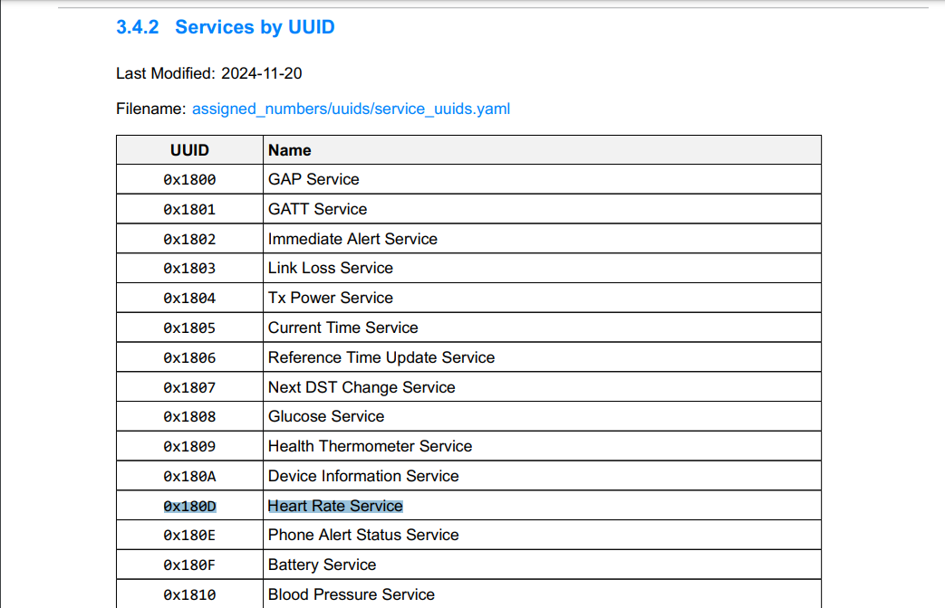
Pre-defined UUID for Heart Rate Monitor characteristic:
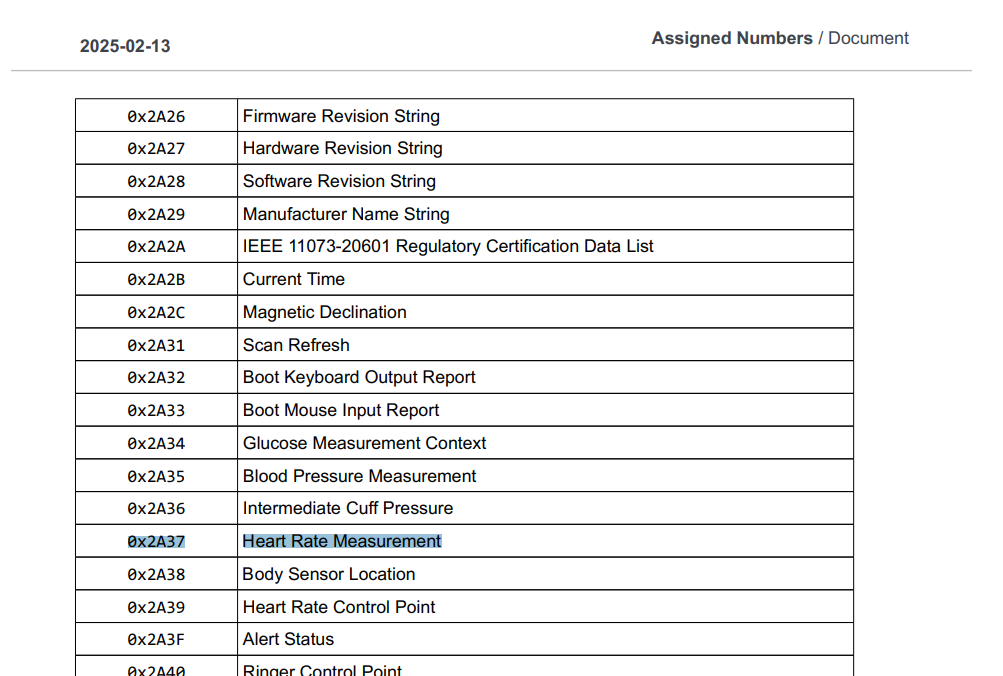
Custom UUID:
Custom UUIDs are used when you're implementing a service that isn't part of the standard, predefined Bluetooth services. However, if you're implementing a common service like a heart rate monitor or battery level, it's best to use the official UUIDs provided in the Bluetooth specifications.
To generate a custom UUID, you can visit the UUID Generator and create unique UUIDs for your services and characteristics.
Writing Embedded Rust Code to Connect Microbit Bluetooth Low Energy (BLE) with a Phone
We have seen what a BLE stack is and understood the basic concepts. Now it's time to use that knowledge in action. We will write a simple (narrator: the author was lying) project that lets the micro:bit send and receive data from a phone.
Our program will include one BLE service called BatteryService. A connected device (like your phone) can either read the current battery level or subscribe to get updates whenever the battery level changes.
Create Project from template
We will use Embassy again, but this time without the BSP. Instead, we will work directly with the embassy-nrf HAL.
cargo generate --git https://github.com/ImplFerris/mb2-template.git --rev 3d07b56
-
When it prompts for a project name, type something like "hell-ble".
-
When it prompts whether to use async, select "true".
-
When it prompts you to select between "BSP" or "HAL", select the option "HAL".
Project Structure
This exercise is adapted from the ble_bas_peripheral_notify.rs example in the nrf-softdevice repository, with some restructuring for clarity. You can explore more examples here.
Below is the structure of the src folder we will build. We'll create a ble module to hold common Bluetooth-related setup and configuration, and a separate service.rs file for the battery service logic.
.
├── ble
│   ├── adv.rs
│   ├── config.rs
│   └── mod.rs
├── main.rs
└── service.rs

1 directory, 5 files
Dependencies
nrf-softdevice crate
This crate provides Rust bindings for Nordic's closed-source SoftDevice Bluetooth stack. The SoftDevice is a precompiled C binary that runs first on startup and then hands control to your app. It's battle tested, pre qualified for bluetooth certification. Learn more: nrf-softdevice GitHub.
We will use this crate to handle Bluetooth in our project. To use it, we must specify the following features for the crate:
-
Exactly one SoftDevice model. Depending on the model, the crate supports different roles. The micro:bit uses the s113 SoftDevice, so we will have to use that. For this model, the crate supports only the peripheral role. It does not support central mode.
-
Exactly one supported nRF chip. For the micro:bit, we already know it uses the nrf52833.
So, we will have to update the Cargo.toml with the following dependencies:
# nrf-softdevice = { version = "0.1.0", features = ["ble-peripheral", "ble-gatt-server", "s113", "nrf52833", "critical-section-impl", "defmt"] }
# To fix a conflict issue, using this latest (at the moment) revision
nrf-softdevice = { git = "https://github.com/embassy-rs/nrf-softdevice/", rev = "5949a5b", features = [
    "ble-peripheral",
    "ble-gatt-server",
    "s113",
    "nrf52833",
    "defmt",
] }
nrf-softdevice-s113 = { version = "0.1.2" }
Along with that, we've enabled a few additional features like ble-peripheral and ble-gatt-server which are needed for our use case.
StaticCell crate
The "StaticCell" crate is useful when you need to initialize a variable at runtime but require it to have a static lifetime.
Update the Cargo.toml with the following dependencies:
static_cell = "2"
Heapless crate
The main idea behind the heapless crate is that it uses data structures that don't need dynamic memory (no heap). Instead, everything is stored in a fixed-size memory area.
Update the Cargo.toml with the following dependencies:
heapless = "0.8"
For example, heapless::Vec is like Rust's regular Vec, but with one big difference: it has a fixed maximum size that you decide ahead of time, and it can't grow beyond that. This is especially useful in Embedded Rust, where heap memory is often not available
Futures
The futures crate provides core tools for writing asynchronous code. We use "select!" and "pin_mut!" macros from it to run the battery level notifier and GATT server tasks concurrently.
futures = { version = "0.3.29", default-features = false }
SoftDevice Firmware
Before we run our Bluetooth program, we need to flash a special firmware called the SoftDevice onto the micro:bit. This firmware is provided by Nordic Semiconductor, the maker of the nRF52833 chip used in the micro:bit v2.
For our chip, we'll use SoftDevice S113, which is a memory-efficient Bluetooth Low Energy (BLE) protocol stack. It supports up to 4 simultaneous BLE connections as a peripheral and can also broadcast data.
Download
-
Go to the Nordic Semi download page: https://www.nordicsemi.com/Products/Development-software/S113/Download
-
Download the package. In my case, I got a file named DeviceDownload.zip.
-
Extract DeviceDownload.zip and you'll find another file: s113_nrf52_7.3.0.zip.
-
Extract that zip too. Inside, you'll see something like this:
.
├── s113_nrf52_7.3.0_API
├── s113_nrf52_7.3.0_license-agreement.txt
├── s113_nrf52_7.3.0_release-notes.pdf
└── s113_nrf52_7.3.0_softdevice.hex

1 directory, 3 files
We are interested in the .hex file. This is a special file format (Intel HEX) that contains binary firmware data in a readable text format.
Flash the SoftDevice
To flash the firmware onto the micro:bit, run this command:
probe-rs download s113_nrf52_7.3.0_softdevice.hex --binary-format Hex --chip nRF52833_xxAA
Just keep in mind that you'll need to repeat this step whenever you come back to the BLE exercises, as other exercises might have overwritten the SoftDevice firmware.
Update memory.x file
After flashing the SoftDevice, we must make sure our Rust program does not overwrite the memory region used by the SoftDevice.
To do that, we update the memory.x linker script. This file defines which regions of memory the Rust compiler can use for your application.
Original memory.x file
MEMORY
{
  FLASH : ORIGIN = 0x00000000, LENGTH = 512K
  RAM : ORIGIN = 0x20000000, LENGTH = 128K
}
Updated memory.x file
MEMORY
{
  /* NOTE 1 K = 1 KiBi = 1024 bytes */
  MBR                               : ORIGIN = 0x00000000, LENGTH = 4K
  SOFTDEVICE                        : ORIGIN = 0x00001000, LENGTH = 112K
  FLASH                             : ORIGIN = 0x0001C000, LENGTH = 396K
  RAM                               : ORIGIN = 0x20003410, LENGTH = 117744
}
This tells the linker to start your program after the SoftDevice's reserved flash and RAM space, preventing memory conflicts at runtime.
Where Do These Values Come From?
These values are based on the pdf document provided along with the hex file (s113_nrf52_7.3.0_release-notes.pdf):
Flash Memory
The SoftDevice uses the first 112 KB (0x1C000) of flash memory, starting from 0x00001000. That means our app should start after 0x0001C000, leaving us with 512 KB - 112 KB - 4 KB (MBR) = 396 KB of usable flash.
RAM Calculation
The minimum RAM required by the SoftDevice depends on how we configure it. According to the release notes, it needs at least 4.4 KB (0x1198), and it can use around 1.8 KB (0x700) for the call stack (in the worst case). But we actually don't need to guess or manually calculate the exact amount to reserve.
The nice part is that the nrf-softdevice crate will tell us exactly how much RAM it needs when the program runs.
Here's the trick: start with a small RAM reservation - for example, try setting the program's RAM start address to 0x20001fa8 (so you're reserving about 8 KB initially). When you flash and run the program, you'll get a log like this:
softdevice RAM: 13328 bytes
So in this case, it needs 13328 bytes, which is 0x3410 in hex. That's why in the final memory.x, we set the program RAM start at 0x20003410. The total RAM on the chip is 128 KB = 131072 bytes, so the remaining RAM for your app becomes:
# remaining_ram = total_ram - softdevice_ram
remaining_ram = 131072 - 13328 = 117744 bytes
That's the usable RAM your program gets after the SoftDevice takes its share.
Special thanks to Dario Nieuwenhuis for helping me understand the RAM calculation for the SoftDevice.
NOTE: You might need to adjust the RAM start and length in memory.x if the SoftDevice configuration changes later. But no need to worry - the nrf-softdevice crate will tell you exactly how much RAM it needs at runtime. We can then adjust them and re-run the program.
RAM : ORIGIN = 0x20003410, LENGTH = 117744
The nrf-softdevice crate will also warn you if you allocate more memory to the SoftDevice than necessary.
BLE Module
Let's start by creating the ble module.
ble/mod.rs file
Here, we define a simple function. It calls softdevice_config (which we will define shortly in config.rs) to get the SoftDevice configuration. Then we enable the SoftDevice using that config.
#![allow(unused)]
fn main() {
pub mod adv;
pub mod config;

use crate::ble::config::softdevice_config;

use {defmt_rtt as _, panic_probe as _};

use nrf_softdevice::Softdevice;

pub fn get_soft_device() -> &'static mut Softdevice {
    let sd_config = softdevice_config();
    Softdevice::enable(&sd_config)
}

}
This gives us an instance of the Softdevice struct. We will call get_soft_device() from the main function later and do further actions on the instance.
ble/adv.rs file
Next, we will create a module to prepare the advertisement data. We already covered the core ideas behind advertising in the GAP section.
We use LegacyAdvertisementBuilder to prepare the advertisement payload. Here, we set the flags to make our device discoverable. For example, we use GeneralDiscovery to keep advertising until connected, and LE_Only to say we don’t support Bluetooth Classic.
We also add the 16-bit UUID for the BATTERY service to let central devices know what we support. The DEVICE_NAME is the constnat ("implRust") that we will define later in the config.rs file.
#![allow(unused)]
fn main() {
use crate::ble::config::DEVICE_NAME;

use {defmt_rtt as _, panic_probe as _};

use nrf_softdevice::ble::{
    advertisement_builder::{
        Flag, LegacyAdvertisementBuilder, LegacyAdvertisementPayload, ServiceList, ServiceUuid16,
    },
    peripheral,
};

static ADV_DATA: LegacyAdvertisementPayload = LegacyAdvertisementBuilder::new()
    .flags(&[Flag::GeneralDiscovery, Flag::LE_Only])
    .services_16(ServiceList::Complete, &[ServiceUuid16::BATTERY])
    .full_name(DEVICE_NAME)
    .build();

static SCAN_DATA: [u8; 0] = [];

pub fn get_adv() -> peripheral::ConnectableAdvertisement<'static> {
    peripheral::ConnectableAdvertisement::ScannableUndirected {
        adv_data: &ADV_DATA,
        scan_data: &SCAN_DATA,
    }
}
}
At the end, we return a ScannableUndirected advertisement type using peripheral::ConnectableAdvertisement. It means our device:
- advertises to any nearby central (not targeting a specific one)
- accepts connection requests
- responds to scan requests with extra info
Softdevice Config - ble/config.rs
Now let's set up the configuration needed to run the SoftDevice. All of the following code goes inside the ble/config.rs file.
Imports
#![allow(unused)]
fn main() {
use {defmt_rtt as _, panic_probe as _};
use core::mem;
use nrf_softdevice::raw;
}
Device Name
First, we define the device name. This will show up when other devices scan for our micro:bit. You are free to modify it with any valid name.
#![allow(unused)]
fn main() {
pub const DEVICE_NAME: &str = "implRust";
}
Clock Config
Bluetooth requires precise timing to manage things like advertising, scanning, and maintaining a connection. That timing depends on a low-frequency clock. Here, we configure the internal RC oscillator as the clock source.
#![allow(unused)]
fn main() {
const fn clock_config() -> Option<raw::nrf_clock_lf_cfg_t> {
    Some(raw::nrf_clock_lf_cfg_t {
        source: raw::NRF_CLOCK_LF_SRC_RC as u8,
        // rc_ctiv: 16,
        rc_ctiv: 4,
        rc_temp_ctiv: 2,
        // accuracy: raw::NRF_CLOCK_LF_ACCURACY_500_PPM as u8,
        accuracy: raw::NRF_CLOCK_LF_ACCURACY_20_PPM as u8,
    })
}
}
The internal RC clock isn't very precise and can slowly become inaccurate over time or with temperature changes (drift over time). To fix that, we tell it to regularly recalibrate:
-
rc_ctiv controls how often the chip performs periodic recalibration to correct any timing drift.
-
rc_temp_ctiv adds another trigger based on temperature changes, so the chip recalibrates if it detects noticeable thermal variation.
-
accuracy: 20 PPM tells the BLE stack how precise the clock is expected to be. A lower PPM value means better timing accuracy, which helps Bluetooth work more reliably.
GAP Connection Config
This sets how many Bluetooth connections your device can handle and how much time is allocated to each connection.
#![allow(unused)]
fn main() {
const fn gap_conn_config() -> Option<raw::ble_gap_conn_cfg_t> {
    Some(raw::ble_gap_conn_cfg_t {
        conn_count: 2,
        event_length: 24,
    })
}
}
-
conn_count: 2 means the device can maintain up to 2 simultaneous Bluetooth connections.
-
event_length sets how long (in 1.25 millisecond units ) the chip reserves for handling each connection during every Bluetooth communication cycle. A value of 24 gives about 30 milliseconds per interval, which is enough time to send and receive data reliably without dropping the connection.
GAP Device Name Setup
This config sets the Bluetooth device name that other devices (like your phone) will see when scanning. By default, SoftDevice uses a generic name, but here we override it with our custom name.
#![allow(unused)]
fn main() {
fn gap_device_name() -> Option<raw::ble_gap_cfg_device_name_t> {
    Some(raw::ble_gap_cfg_device_name_t {
        p_value: DEVICE_NAME.as_ptr() as _,
        current_len: DEVICE_NAME.len() as u16,
        max_len: DEVICE_NAME.len() as u16,
        write_perm: unsafe { mem::zeroed() },
        _bitfield_1: raw::ble_gap_cfg_device_name_t::new_bitfield_1(
            raw::BLE_GATTS_VLOC_STACK as u8,
        ),
    })
}
}
- p_value points to the memory where our custom device name ("implRust") is stored.
- current_len and max_len define the current and maximum length of the name.
- write_perm controls whether the name can be changed by connected clients. We're using zeroed() here to disable write access.
- _bitfield_1 includes vloc, which sets where the name is stored. We use BLE_GATTS_VLOC_STACK, meaning the name is stored in flash (non-volatile memory) and not writable at runtime.
GAP Role Count
This configuration sets limits on how many Bluetooth operations your device can handle at the same time.
#![allow(unused)]
fn main() {
const fn gap_role_count() -> Option<raw::ble_gap_cfg_role_count_t> {
    Some(raw::ble_gap_cfg_role_count_t {
        adv_set_count: raw::BLE_GAP_ADV_SET_COUNT_DEFAULT as u8,
        periph_role_count: raw::BLE_GAP_ROLE_COUNT_PERIPH_DEFAULT as u8,
    })
}
}
-
The adv_set_count is how many advertising handles we want. We leave it to default.
-
periph_role_count defines how many devices the micro:bit can be connected to at the same time while acting as a peripheral. Again, we use the default setting (which allows one connection).
GATT Connection Config
This sets the size of the ATT (Attribute Protocol) packet. In simple terms, it controls how much data can be sent or received in one go over BLE.
#![allow(unused)]
fn main() {
const fn gatt_conn_config() -> Option<raw::ble_gatt_conn_cfg_t> {
    Some(raw::ble_gatt_conn_cfg_t { att_mtu: 256 })
}
}
att_mtu stands for Attribute Maximum Transmission Unit . It defines how much data can be sent in one go between devices. The default MTU is 23 bytes, which is quite small. We're bumping it up to 256 so that we can send or receive larger chunks of data in a single BLE packet. This helps improve throughput and reduces the overhead of sending tiny pieces
GATT Attribute Table Size
This configuration sets the size of the attribute table , which is used to store data like service definitions, characteristics, and descriptors that other devices can read or write over BLE.
#![allow(unused)]
fn main() {
const fn gatts_attr_tab_size() -> Option<raw::ble_gatts_cfg_attr_tab_size_t> {
    Some(raw::ble_gatts_cfg_attr_tab_size_t {
        attr_tab_size: raw::BLE_GATTS_ATTR_TAB_SIZE_DEFAULT,
    })
}
}
We're using the default size, which is usually enough for most small BLE setups. But if you add many services, you may need to increase this. Make sure the size is a multiple of 4, or it will throw an error.
Putting It All Together
This function gathers all the configs we defined above and builds the final config that will be passed to Softdevice::enable()
#![allow(unused)]
fn main() {
// Softdevice config
pub fn softdevice_config() -> nrf_softdevice::Config {
    nrf_softdevice::Config {
        clock: clock_config(),
        conn_gap: gap_conn_config(),
        conn_gatt: gatt_conn_config(),
        gatts_attr_tab_size: gatts_attr_tab_size(),
        gap_role_count: gap_role_count(),
        gap_device_name: gap_device_name(),
        ..Default::default()
    }
}
}
The full content of the config.rs
#![allow(unused)]
fn main() {
use {defmt_rtt as _, panic_probe as _};

use core::mem;

use nrf_softdevice::raw;

pub const DEVICE_NAME: &str = "implRust";

const fn clock_config() -> Option<raw::nrf_clock_lf_cfg_t> {
    Some(raw::nrf_clock_lf_cfg_t {
        source: raw::NRF_CLOCK_LF_SRC_RC as u8,
        // rc_ctiv: 16,
        rc_ctiv: 4,
        rc_temp_ctiv: 2,
        // accuracy: raw::NRF_CLOCK_LF_ACCURACY_500_PPM as u8,
        accuracy: raw::NRF_CLOCK_LF_ACCURACY_20_PPM as u8,
    })
}

const fn gap_conn_config() -> Option<raw::ble_gap_conn_cfg_t> {
    Some(raw::ble_gap_conn_cfg_t {
        conn_count: 2,
        event_length: 24,
    })
}

const fn gatt_conn_config() -> Option<raw::ble_gatt_conn_cfg_t> {
    Some(raw::ble_gatt_conn_cfg_t { att_mtu: 256 })
}

fn gap_device_name() -> Option<raw::ble_gap_cfg_device_name_t> {
    Some(raw::ble_gap_cfg_device_name_t {
        p_value: DEVICE_NAME.as_ptr() as _,
        current_len: DEVICE_NAME.len() as u16,
        max_len: DEVICE_NAME.len() as u16,
        write_perm: unsafe { mem::zeroed() },
        _bitfield_1: raw::ble_gap_cfg_device_name_t::new_bitfield_1(
            raw::BLE_GATTS_VLOC_STACK as u8,
        ),
    })
}

const fn gap_role_count() -> Option<raw::ble_gap_cfg_role_count_t> {
    Some(raw::ble_gap_cfg_role_count_t {
        adv_set_count: raw::BLE_GAP_ADV_SET_COUNT_DEFAULT as u8,
        periph_role_count: raw::BLE_GAP_ROLE_COUNT_PERIPH_DEFAULT as u8,
    })
}

const fn gatts_attr_tab_size() -> Option<raw::ble_gatts_cfg_attr_tab_size_t> {
    Some(raw::ble_gatts_cfg_attr_tab_size_t {
        attr_tab_size: raw::BLE_GATTS_ATTR_TAB_SIZE_DEFAULT,
    })
}

// Softdevice config
pub fn softdevice_config() -> nrf_softdevice::Config {
    nrf_softdevice::Config {
        clock: clock_config(),
        conn_gap: gap_conn_config(),
        conn_gatt: gatt_conn_config(),
        gatts_attr_tab_size: gatts_attr_tab_size(),
        gap_role_count: gap_role_count(),
        gap_device_name: gap_device_name(),
        ..Default::default()
    }
}

}
Reference
GATT Service - "service.rs"
Our program defines a single GATT service called the Battery Service.
Battery Service
The nrf_softdevice crate provides a gatt_service macro along with a characteristic attribute to define GATT services and characteristics. We can specify the UUID for both the service and its characteristics.
In this example, we use the standard 16-bit UUID 0x180F, which is the predefined identifier for the Battery Service . The battery level characteristic uses the standard UUID 0x2A19, which represents the current battery level.
If you're implementing a custom, non-standard service or characteristic, you should generate and use a custom 128-bit UUID instead.
#![allow(unused)]

fn main() {
#[nrf_softdevice::gatt_service(uuid = "180f")]
pub struct BatteryService {
    #[characteristic(uuid = "2a19", read, notify)]
    battery_level: i16,
}
}
We also specify permissions using the read and notify keywords. read allows connected devices to fetch the battery level whenever they want. notify lets us push updates to the client when the battery level changes.
GATT Server
A GATT server is responsible for hosting services and characteristics that can be accessed by a connected GATT client (e.g., a smartphone or computer).
We define a Server struct with a field of type BatteryService. We then mark this struct with the #[gatt_server] attribute macro. This generates all the necessary boilerplate code and provides us with useful functions like Server::new() to initialize the GATT server.
#![allow(unused)]
fn main() {
#[nrf_softdevice::gatt_server]
pub struct Server {
    bas: BatteryService,
}
}
The full code of service.rs
We've added a method to the Server struct called "notify_battery_value", which will run in the background once a connection is established. This is not the actual battery status. We're just simulating it by increasing and decreasing the battery level to demonstrate.
Inside that function, we call self.bas.battery_level_notify() with the current battery level. If the client has subscribed to notifications for the battery level characteristic, they'll receive updates automatically. Otherwise, the value is still updated and can be read on demand by the client.
#![allow(unused)]

fn main() {
use defmt::{info, unwrap};
use embassy_time::Timer;
use nrf_softdevice::ble::Connection;

#[nrf_softdevice::gatt_service(uuid = "180f")]
pub struct BatteryService {
    #[characteristic(uuid = "2a19", read, notify)]
    battery_level: i16,
}

#[nrf_softdevice::gatt_server]
pub struct Server {
    bas: BatteryService,
}

impl Server {
    pub async fn notify_battery_value(&self, connection: &Connection) {
        let mut battery_level = 100;
        let mut charging = false;
        loop {
            if battery_level < 20 {
                charging = true;
            } else if battery_level >= 100 {
                charging = false;
            }

            if charging {
                battery_level += 5;
            } else {
                battery_level -= 5;
            }

            match self.bas.battery_level_notify(connection, &battery_level) {
                Ok(_) => info!("Battery Level: {=i16}", &battery_level),
                Err(_) => unwrap!(self.bas.battery_level_set(&battery_level)),
            };

            Timer::after_secs(2).await
        }
    }
}
}
Main
Now, we will work on the main.rs file. First, We modify the main.rs file with the following required imports:
#![allow(unused)]
#![no_std]
#![no_main]
fn main() {
mod ble;
mod service;
use crate::ble::get_soft_device;
use crate::service::*;

use {defmt_rtt as _, panic_probe as _};

use defmt::{info, unwrap};
use embassy_executor::Spawner;
use embassy_nrf::interrupt;
use futures::future::{Either, select};
use futures::pin_mut;
use nrf_softdevice::Softdevice;
use nrf_softdevice::ble::{gatt_server, peripheral};
}
Priority
To ensure safe interaction between the SoftDevice (which handles BLE) and your application code, the application must run at a lower interrupt priority than the SoftDevice .
The SoftDevice uses high interrupt priority levels for BLE operation. The application must not use a higher or equal priority level for its own interrupts.
The following function configures the nRF driver to use priority level 2 for key hardware interrupts like GPIOTE and TIMER:
#![allow(unused)]
fn main() {
// Application must run at a lower priority than softdevice
fn nrf_config() -> embassy_nrf::config::Config {
    let mut config = embassy_nrf::config::Config::default();
    config.gpiote_interrupt_priority = interrupt::Priority::P2;
    config.time_interrupt_priority = interrupt::Priority::P2;
    config
}
}
Clear any existing code inside the main function and add this line to initialize the HAL with this config:
async fn main(spawner: Spawner) {
    let _ = embassy_nrf::init(nrf_config());

    // We will add remaining code here followed by the above line
}
Initialize Softdevice
We first get the Softdevice instance by calling get_soft_device function, which we defined in the ble module. We use this to initialize the Server struct, which we defined in the service module.
Then we run sd.run() in the background with the help of embassy task.
#![allow(unused)]
fn main() {
let sd = get_soft_device();
let server = unwrap!(Server::new(sd));
unwrap!(spawner.spawn(softdevice_task(sd)));
}
We define the task like this:
#![allow(unused)]
fn main() {
#[embassy_executor::task]
pub async fn softdevice_task(sd: &'static Softdevice) -> ! {
    sd.run().await
}
}
Connection
Now we enter the main loop. In each loop, we advertise to accept a BLE connection. Once a connection is established, we start the GATT server and the battery notifier concurrently.
There are multiple things going on here; we will explain them one by one.
#![allow(unused)]
fn main() {
loop {
        let config = peripheral::Config::default();

        let adv = ble::adv::get_adv();

        let conn = unwrap!(peripheral::advertise_connectable(sd, adv, &config).await);
        info!("advertising done! I have a connection.");

        let battery_fut = server.notify_battery_value(&conn);
        let gatt_fut = gatt_server::run(&conn, &server, |e| match e {
            ServerEvent::Bas(e) => match e {
                BatteryServiceEvent::BatteryLevelCccdWrite { notifications } => {
                    info!("battery notifications: {}", notifications)
                }
            },
        });

        pin_mut!(battery_fut);
        pin_mut!(gatt_fut);

        match select(battery_fut, gatt_fut).await {
            Either::Left((_, _)) => {
                info!("Battery Notification encountered an error and stopped!")
            }
            Either::Right((e, _)) => {
                info!("gatt_server run exited with error: {:?}", e);
            }
        };
    }
}
Advertise
We first initialize the default config for advertising with "peripheral::Config::default()". Then we get the advertisement payload by calling get_adv(), which we defined earlier. Next, we call "advertise_connectable" with the advertisement data and config.
#![allow(unused)]
fn main() {
let conn = unwrap!(peripheral::advertise_connectable(sd, adv, &config).await);
}
This line starts broadcasting advertisement packets and waits until a central device (like a smartphone) connects . Once a connection is established, it returns a Connection object that we'll use to interact with the connected client.
GATT connection
Once we get a connection, we call "notify_battery_value" and "gatt_server::run". Both are async functions. However, if you notice, we have not used ".await". Instead, we store the futures in variables and call pin_mut! on them.
#![allow(unused)]
fn main() {
let battery_fut = server.notify_battery_value(&conn);
let gatt_fut = gatt_server::run(&conn, &server, |e| match e {
    ServerEvent::Bas(e) => match e {
        BatteryServiceEvent::BatteryLevelCccdWrite { notifications } => {
            info!("battery notifications: {}", notifications)
        }
    },
});
}
The gatt_server::run function runs the GATT server and receives events using the callback we provide. These events are represented by an enum called ServerEvent, which is automatically generated by the #[gatt_server] proc macro from the nrf_softdevice crate (we annotated the Server struct in the service.rs file with this macro).
We then use select on the two pinned futures. This waits until one of them completes and automatically cancels the other.
-
The battery notifier task runs in an infinite loop, continuously sending updates, and only exits if there is an error.
-
The GATT server also runs continuously until it hits an error or the client disconnects (such as with a DisconnectError).
This setup ensures that when either side exits, we cleanly break out and restart the loop to accept a new connection.
The full content of main.rs
#![no_std]
#![no_main]
mod ble;
mod service;
use crate::ble::get_soft_device;
use crate::service::*;

use {defmt_rtt as _, panic_probe as _};

use defmt::{info, unwrap};
use embassy_executor::Spawner;
use embassy_nrf::interrupt;
use futures::future::{Either, select};
use futures::pin_mut;
use nrf_softdevice::Softdevice;
use nrf_softdevice::ble::{gatt_server, peripheral};

// Application must run at a lower priority than softdevice
fn nrf_config() -> embassy_nrf::config::Config {
    let mut config = embassy_nrf::config::Config::default();
    config.gpiote_interrupt_priority = interrupt::Priority::P2;
    config.time_interrupt_priority = interrupt::Priority::P2;
    config
}

#[embassy_executor::main]
async fn main(spawner: Spawner) {
    // First we get the peripherals access crate.
    let _ = embassy_nrf::init(nrf_config());

    let sd = get_soft_device();
    let server = unwrap!(Server::new(sd));
    unwrap!(spawner.spawn(softdevice_task(sd)));

    loop {
        let config = peripheral::Config::default();

        let adv = ble::adv::get_adv();

        let conn = unwrap!(peripheral::advertise_connectable(sd, adv, &config).await);
        info!("advertising done! I have a connection.");

        let battery_fut = server.notify_battery_value(&conn);
        let gatt_fut = gatt_server::run(&conn, &server, |e| match e {
            ServerEvent::Bas(e) => match e {
                BatteryServiceEvent::BatteryLevelCccdWrite { notifications } => {
                    info!("battery notifications: {}", notifications)
                }
            },
        });

        pin_mut!(battery_fut);
        pin_mut!(gatt_fut);

        match select(battery_fut, gatt_fut).await {
            Either::Left((_, _)) => {
                info!("Battery Notification encountered an error and stopped!")
            }
            Either::Right((e, _)) => {
                info!("gatt_server run exited with error: {:?}", e);
            }
        };
    }
}

#[embassy_executor::task]
pub async fn softdevice_task(sd: &'static Softdevice) -> ! {
    sd.run().await
}
Connect Your Rust-Powered microbit to a Phone Using nRF Connect
The coding part is done. Now let's run the program and connect to the micro:bit using the nRF Connect mobile app. There is also a desktop version of the app available if you prefer to use your computer instead.
Clone the existing project
If you run into any issues, feel free to clone (or refer to) the project I've created and navigate to the "hello-ble" folder.
git clone https://github.com/ImplFerris/microbit-projects
cd microbit-projects/hal-embassy/hello-ble
Flash
You can flash the program into the micro:bit.
cargo run
You should see output like this:
softdevice RAM: 13328 bytes
If you encounter a panic about insufficient RAM, or a warning that you've allocated more RAM than needed, follow the steps in this guide to adjust the SoftDevice RAM settings.
How to connect?
Once you flash the code, open the nRF Connect mobile app. Scan for the Bluetooth name we set (mine is "implRust") and connect to it.

If successful, you should get the following gets printed in the system console
advertising done! I have a connection.
The app will show the supported service and characteristics.
Reading the value
To read the current battery level, tap the icon highlighted in the image below:

Subscribing to Notifications
To receive automatic updates when the battery level changes, tap the icon with three downward arrows under the characteristic (as shown in the image). This subscribes your phone to notifications from the micro:bit.

What's Next?
All we did here was use the demo mobile app provided by Nordic. In a real-life scenario, you might need to build your own app or figure out how to send data in a way that matches an existing app.
TrouBLE - Bluetooth Low Energy (BLE) Host implementation for embedded devices written in Rust
In the previous chapter, we used the nrf-softdevice crate to send data (battery level) from the micro:bit to a phone. Now, we will introduce you to TrouBLE, a cross-platform BLE Host stack written in Rust. TrouBLE is still in earlier stage (the first version was released in March 2025 on crates.io)
TrouBLE is a Bluetooth Low Energy (BLE) Host implementation for embedded devices written in Rust, with a future goal of qualification.
BLE Host
In the BLE stack, the system is split into two parts:
- Controller : Handles the low-level radio operations.
- Host : Manages the higher-level protocols like GATT, L2CAP, ATT, and SMP.

These two components communicate via the Host Controller Interface (HCI); a standardized protocol that can run over various transports such as UART, USB, or even in-memory shared buffers.
Controller-Agnostic
This separation allows the same Host stack to work across different controllers. TrouBLE works with any controller that implements the required traits from bt-hci crate (bt-hci is like embedded-hal but for bluetooth communications). That means you can write one BLE application in Rust and reuse it across platforms like:
- Nordic nRF52 (via SoftDevice Controller)
- ESP32
- Raspberry Pi Pico W
- Apache NimBLE
- UART HCI
More platforms may be supported in the future. You can refer to the TrouBLE GitHub repository for the latest list of supported controllers.
For microbit(more precisely, for nRF52) - Softdevice vs Softdevice Controller
In the previous chapter, we used the nrf-softdevice crate. This approach requires you to flash the SoftDevice firmware onto the device and configure the memory layout (via memory.x). The nrf-softdevice crate acts as a Rust wrapper around Nordic's original SoftDevice. The Softdevice is a complete, closed-source, precompiled Bluetooth stack. The SoftDevice includes both the Controller (Link Layer) and Host (GAP, GATT, L2CAP, etc.) layers, providing a full BLE implementation.
In contrast, the SoftDevice Controller is a newer solution designed for the nRF52 and nRF53 series. Unlike the original SoftDevice, this is only the Controller part. It's not a Rust library by itself; the nrf-sdc crate provides Rust bindings to it; This crate implements the bt-hci traits. However, since it only handles the controller side, you still need a Host stack to complete the BLE functionality - and that's where Trouble (pun intended) comes in. TrouBLE is the Host stack that can pair with the SoftDevice Controller.
- Old approach: Uses the full SoftDevice (controller + host) with the nrf-softdevice crate. Fully certified.
- New approach: Uses the SoftDevice Controller with the nrf-sdc crate and the Rust-based Trouble host stack. More flexible, but would need certification for commercial use.
External Components
So far, we have worked with the built-in features of the micro:bit v2. From now on, we will be using external components such as sensors, displays, and input devices. To follow along, you may need to purchase extra parts like modules, jumper wires, and a breadboard.
Alligator clip wires
Alligator clip wires (also called crocodile clips) are a simple way to connect external components to the micro:bit's edge connector, especially the large pins labeled P0, P1, and P2.
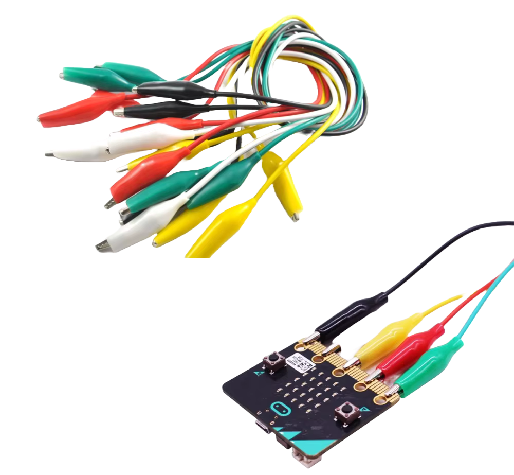
These clips come in different styles:
-
Double-ended: Alligator clips on both sides.
-
Hybrid: One end is an alligator clip, and the other end is a male or female header for plugging into breadboards or modules.
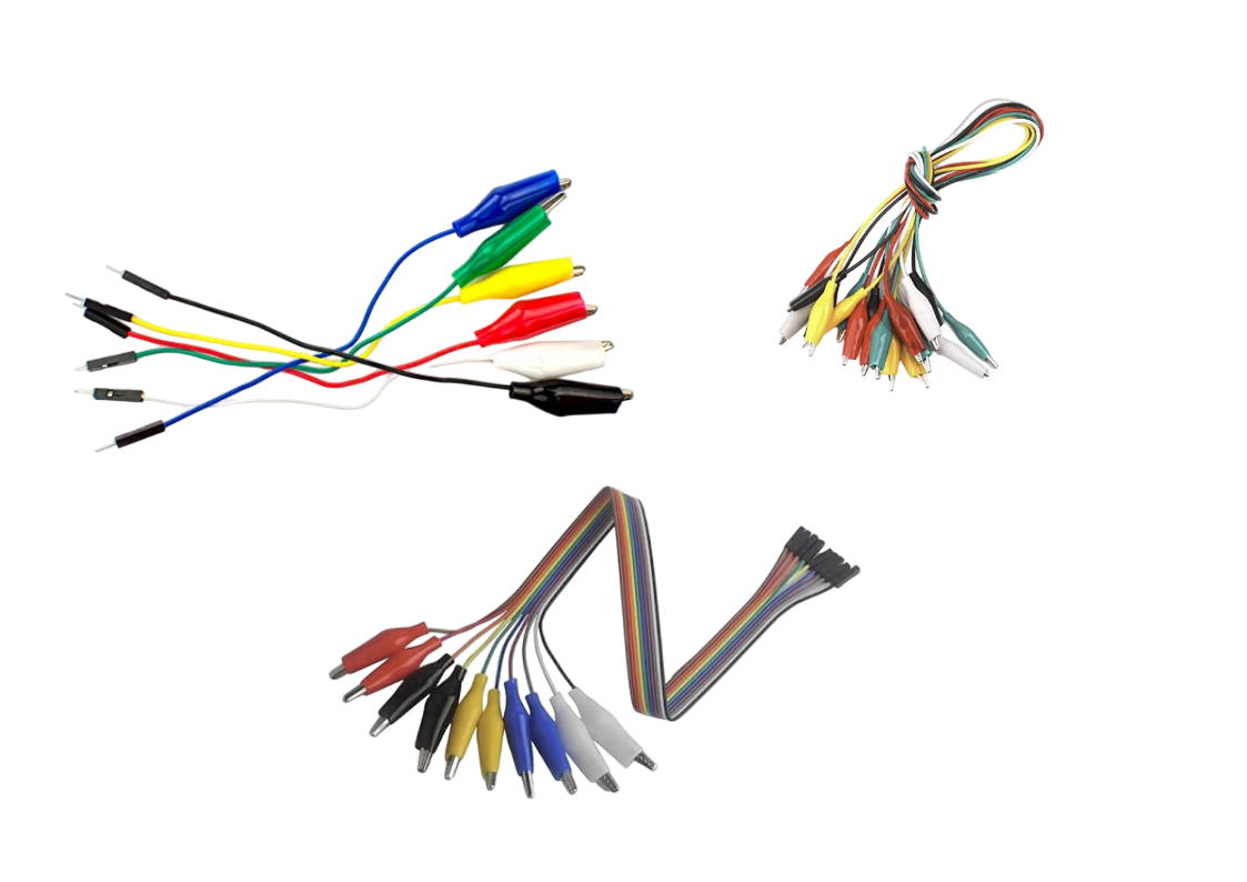
Breadboard
You can manage most of the exercises without a breadboard. However, having one can be helpful in some cases. A breadboard allows you to build circuits without soldering. It makes it easier to connect multiple components, organize your wiring, and experiment with different setups.
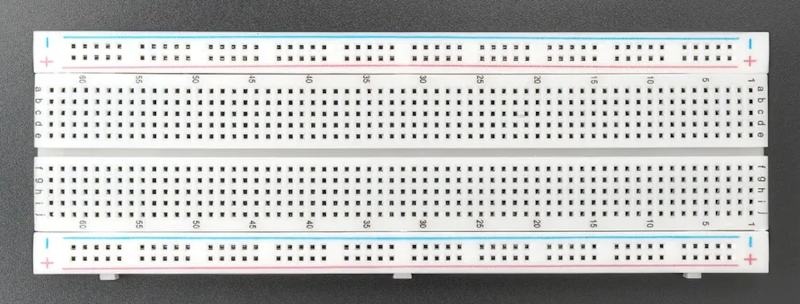
Expansion board
The microbit's edge connector exposes many of its GPIO pins, power lines, and communication interfaces (such as I2C, SPI, and UART). While a few pins (like P0, P1, and P2) are accessible as large pads, the rest are too small and closely spaced to connect directly.
In some projects, you might need an expansion board(breakout board). This plugs into the edge connector and gives you access to all the pins through standard headers, making it much easier to connect components using jumper wires and a breadboard.
You can see the list of expansion board on the microbit official website here. You can also search in your local e-commerce website or shop to find cheaper alternative. Also make sure it is for microbit "v2"
Don't buy unless you need it. We wont be using this in our exercises.
LDR (Light Dependent Resistor)
We're now entering the next stage of our book, where we begin using external components. In this section, we'll start with an LDR (Light Dependent Resistor), also known as a photocell or photoresistor, and connect it to the Micro:bit.
An LDR changes its resistance based on the amount of light falling on it. The brighter the light, the lower the resistance, and the dimmer the light, the higher the resistance. This makes it ideal for applications like light sensing, automatic lighting, or monitoring ambient light levels.
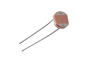
Components Needed:
- LDR (Light Dependent Resistor)
- Resistor (typically 10kΩ): needed to create voltage divider
- Alligator Clips: You can use either hybrid clips or double-ended alligator clips. In most cases, double-ended clips should be sufficient.
Prerequisite
To work with this, you should get familiar with what a voltage divider is and how it works. You also need to understand what ADC is and how it functions. In this sections, we will introduce these concepts.
Voltage Divider
A voltage divider is a simple circuit that reduces an input voltage (\( V_{in} \)) to a lower output voltage (\( V_{out} \)) using two series resistors. The resistor connected to the input voltage is called \( R_{1} \), and the other resistor is \( R_{2} \). The output voltage is taken from the junction between \( R_{1} \) and \( R_{2} \), producing a fraction of \( V_{in} \).
Circuit
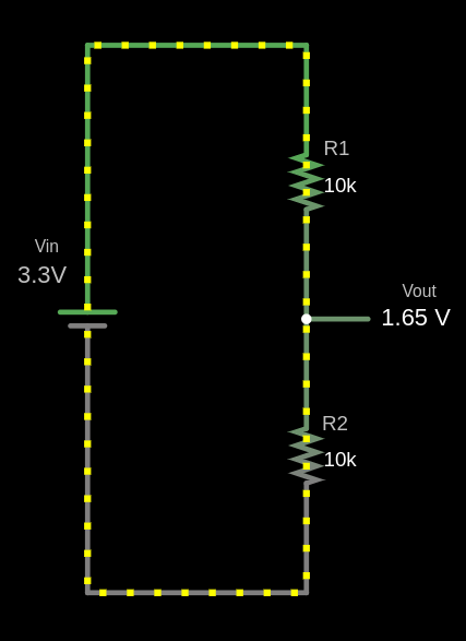
The output voltage (Vout) is calculated using this formula:
\[ V_{out} = V_{in} \times \frac{R_2}{R_1 + R_2} \]
Example Calculation for \( V_{out} \)
Given:
- \( V_{in} = 3.3V \)
- \( R_1 = 10 k\Omega \)
- \( R_2 = 10 k\Omega \)
Substitute the values:
\[ V_{out} = 3.3V \times \frac{10 k\Omega}{10 k\Omega + 10 k\Omega} = 3.3V \times \frac{10}{20} = 3.3V \times 0.5 = 1.65V \]
The output voltage \( V_{out} \) is 1.65V.
fn main() {
    // You can edit the code
    // You can modify values and run the code
    let vin: f64 = 3.3;
    let r1: f64 = 10000.0;
    let r2: f64 = 10000.0;

    let vout = vin * (r2 / (r1 + r2));

    println!("The output voltage Vout is: {:.2} V", vout);
}
Use cases
Voltage dividers are used in applications like potentiometers, where the resistance changes as the knob is rotated, adjusting the output voltage. They are also used to measure resistive sensors such as light sensors and thermistors, where a known voltage is applied, and the microcontroller reads the voltage at the center node to determine sensor values like temperature.
Voltage Divider Simulation
Formula: Vout = Vin × (R2 / (R1 + R2))
Filled Formula: Vout = 3.3 × (10000 / (10000 + 10000))
Output Voltage (Vout): 1.65 V
Simulator in Falstad website
I used the website https://www.falstad.com/circuit/ to create the diagram. It's a great tool for drawing circuits. You can download the file I created, voltage-divider.circuitjs.txt, and import it to experiment with the circuit.
How LDR works?
We have already given an introduction to what an LDR is. Let me repeat it again: an LDR changes its resistance based on the amount of light falling on it. The brighter the light, the lower the resistance, and the dimmer the light, the higher the resistance.
Dracula: Think of the LDR as Dracula. In sunlight, he gets weaker (just like the resistance gets lower). But in the dark, he gets stronger (just like the resistance gets higher).
We will not cover what kind of semiconductor materials are used to make an LDR, nor why it behaves this way in depth. I recommend you read this article and do further research if you are interested.
Example output for full brightness
The resistance of the LDR is low when exposed to full brightness, causing the output voltage(\( V_{out} \)) to be significantly lower.
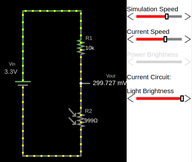
Example output for low light
With less light, the resistance of the LDR increases and the output voltage increase.
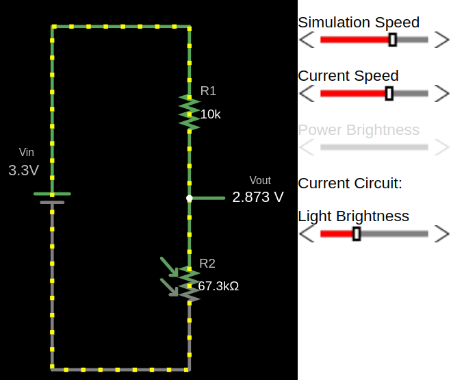
Example output for full darkness
In darkness, the LDR's resistance is high, resulting in a higher output voltage (\( V_{out} \)).
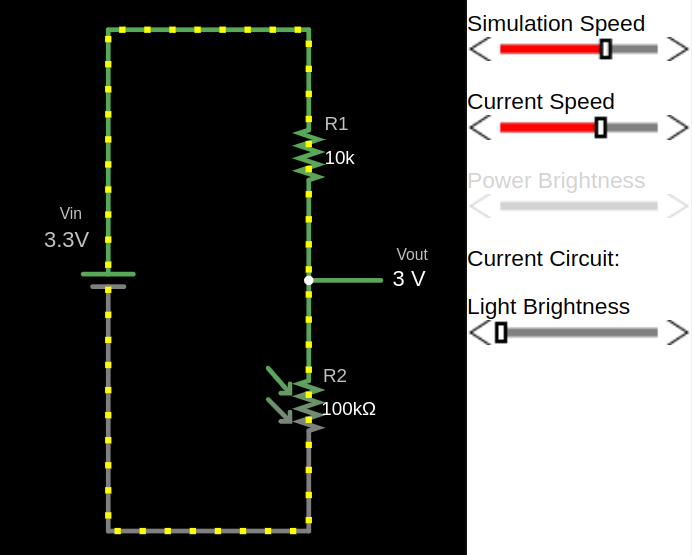
Simulation of LDR in Voltage Divider
You can adjust the brightness value and observe how the resistance of R2 (which is the LDR) changes. Also, you can watch how the \( V_{out} \) voltage changes as you increase or decrease the brightness.
50%
Formula: \( V_\text{out} = V_\text{in} \times \frac{R_2}{R_1 + R_2} \)
Filled Formula: Vout = 3.3 × 999 / (10000 + 999)
Output Voltage (Vout): 0.25 V
Circuitjs
The above diagrams are i created using the Falstad website. You can import the circuit file I created, voltage-divider-ldr.circuitjs.txt, import into the Falstad site and play around.
ADC (Analog to Digital Converter)
An Analog-to-Digital Converter (ADC) is a device used to convert analog signals (continuous signals like sound, light, or temperature) into digital signals (discrete values, typically represented as 1s and 0s). This conversion is necessary for digital systems like microcontrollers (e.g., nrF52833, Raspberry Pi Pico) to interact with the real world. For example, sensors that measure temperature or sound produce analog signals, which need to be converted into digital format for processing by digital devices.
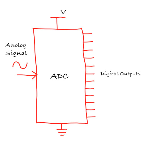
ADC Resolution
The resolution of an ADC refers to how precisely the ADC can measure an analog signal. It is expressed in bits, and the higher the resolution, the more precise the measurements.
- 8-bit ADC produces digital values between 0 and 255.
- 10-bit ADC produces digital values between 0 and 1023.
- 12-bit ADC produces digital values between 0 and 4095.
The resolution of the ADC can be expressed as the following formula: \[ \text{Resolution} = \frac{\text{Vref}}{2^{\text{bits}} - 1} \]
Microbit v2 (nRF52833)
The nRF52833 has 12-bit, 8 channel Analogue to Digital Converter (ADC). So, it provides values ranging from 0 to 4095 (4096 possible values)
\[ \text{Resolution} = \frac{3.3V}{2^{12} - 1} = \frac{3.3V}{4095} \approx 0.000805 \text{V} \approx 0.8 \text{mV} \]
ADC Value and LDR Resistance in a Voltage Divider
In a voltage divider with an LDR and a fixed resistor, the output voltage \( V_{\text{out}} \) is given by:
\[ V_{\text{out}} = V_{\text{in}} \times \frac{R_{\text{LDR}}}{R_{\text{LDR}} + R_{\text{fixed}}} \]
It is same formula as explained in the previous chapter, just replaced the \({R_2}\) with \({R_{\text{LDR}}}\) and \({R_1}\) with \({R_{\text{fixed}}}\)
- Bright light (low LDR resistance): \( V_{\text{out}} \) decreases, resulting in a lower ADC value.
- Dim light (high LDR resistance): \( V_{\text{out}} \) increases, leading to a higher ADC value.
Example ADC value calculation:
Bright light:
Let's say the Resistence value of LDR is \(1k\Omega\) in the bright light (and we have \(10k\Omega\) fixed resistor).
\[ V_{\text{out}} = 3.3V \times \frac{1k\Omega}{1k\Omega + 10k\Omega} \approx 0.3V \]
The ADC value is calculated as: \[ \text{ADC value} = \left( \frac{V_{\text{out}}}{V_{\text{ref}}} \right) \times (2^{12} - 1) \approx \left( \frac{0.3}{3.3} \right) \times 4095 \approx 372 \]
Darkness:
Let's say the Resistence value of LDR is \(140k\Omega \) in very low light.
\[ V_{\text{out}} = 3.3V \times \frac{140k\Omega}{140k\Omega + 10k\Omega} \approx 3.08V \]
The ADC value is calculated as: \[ \text{ADC value} = \left( \frac{V_{\text{out}}}{V_{\text{ref}}} \right) \times (2^{12} - 1) \approx \left( \frac{3.08}{3.3} \right) \times 4095 = 3822 \]
Converting ADC value back to voltage:
Now, if we want to convert the ADC value back to the input voltage, we can multiply the ADC value by the resolution (0.8mV).
For example, let's take an ADC value of 3822:
\[ \text{Voltage} = 3822 \times 0.8mV = 3057.6mV \approx 3.06V \]
Single Ended vs Differential Mode
Single-ended Mode
In single-ended mode, the ADC measures the voltage on one signal pin with respect to ground. You can think of it like measuring how high a point is above the floor. This method is simple to use and requires only one input pin. However, it is more vulnerable to electrical noise, especially when using long wires, and it cannot measure negative voltages.
This mode is commonly used in situations such as reading light levels using an LDR, measuring distances with infrared or ultrasonic sensors, and monitoring air or gas quality using analog sensor modules. The calculations we discussed earlier are all based on single-ended ADC measurements.
Differential Mode
In differential mode, the ADC measures the difference between two input pins, completely ignoring the ground. It is like comparing the height difference between two people, no matter where they are standing.
This mode helps cancel out common noise seen on both inputs and is capable of detecting very small changes in voltage, including signals that swing both above and below ground. While it does require an additional pin and a slightly more complex setup, it is useful in high-precision applications such as measuring temperature using thermocouples or detecting pressure and force using strain gauges.
Reference
Analog to Digital Converter (ADC) in nRF52833
The nRF52833 features a 12-bit Successive Approximation Register (SAR) ADC, referred to by Nordic as the SAADC, and supports up to 8 input channels for analog measurements.
Here is a mapping of analog input channels (AIN0 to AIN7) to their corresponding GPIO pins on the nRF52833.
| Analog Input | GPIO Pin |
|---|---|
| AIN0 | P0.02 |
| AIN1 | P0.03 |
| AIN2 | P0.04 |
| AIN3 | P0.05 |
| AIN4 | P0.28 |
| AIN5 | P0.29 |
| AIN6 | P0.30 |
| AIN7 | P0.31 |
Microbit Pin Layout

This table shows which analog input channels on the nRF52833 are accessible from the micro:bit v2 edge connector. The large pins (Ring 0, Ring 1 and Ring2) provide safe and direct access to analog input without conflict. The small pins (3, 4, 10) are also ADC-capable but are shared with the LED matrix, so they should only be used for analog input when the display is disabled.
| microbit Pin | GPIO (nRF52833) | Analog Input | Accessible via | Shared With | Notes |
|---|---|---|---|---|---|
| 0 | P0.02 | AIN0 | Large ring | — | Fully available |
| 1 | P0.03 | AIN1 | Large ring | — | Fully available |
| 2 | P0.04 | AIN2 | Large ring | — | Fully available |
| 3 | P0.31 | AIN7 | Small pin 3 | LED Column 3 | Only usable when display is off |
| 4 | P0.28 | AIN4 | Small pin 4 | LED Column 1 | Only usable when display is off |
| 10 | P0.30 | AIN6 | Small pin 10 | LED Column 5 | Only usable when display is off |
Reference
- Edge Connector & micro:bit pinout
- micro:bit pins
- nR52833 Datasheet
- Differential and Single-Ended ADC Paper
Automatic LED Control Based on Ambient Light using an LDR and Microbit
In this exercise, we'll control an LED based on ambient light levels. The goal is to automatically turn on the LED in low light conditions.
You can try this in a closed room by turning the room light on and off. When you turn off the room-light, the LED should turn on, given that the room is dark enough, and turn off again when the room-light is switched back on. Alternatively, you can adjust the sensitivity threshold or cover the light sensor (LDR) with your hand or some object to simulate different light levels.
Note: You may need to adjust the ADC threshold based on your room's lighting conditions and the specific LDR you are using.
Circuit to connect LDR with Microbit
- One side of the LDR is connected to Ground
- The other side of the LDR is connected to Pin 0 (Analog In) on the Micro:bit.
- A 10K ohm resistor is connected between Pin 0 and 3V.
- This creates a voltage divider circuit, where the voltage at Pin 0 changes based on light levels.
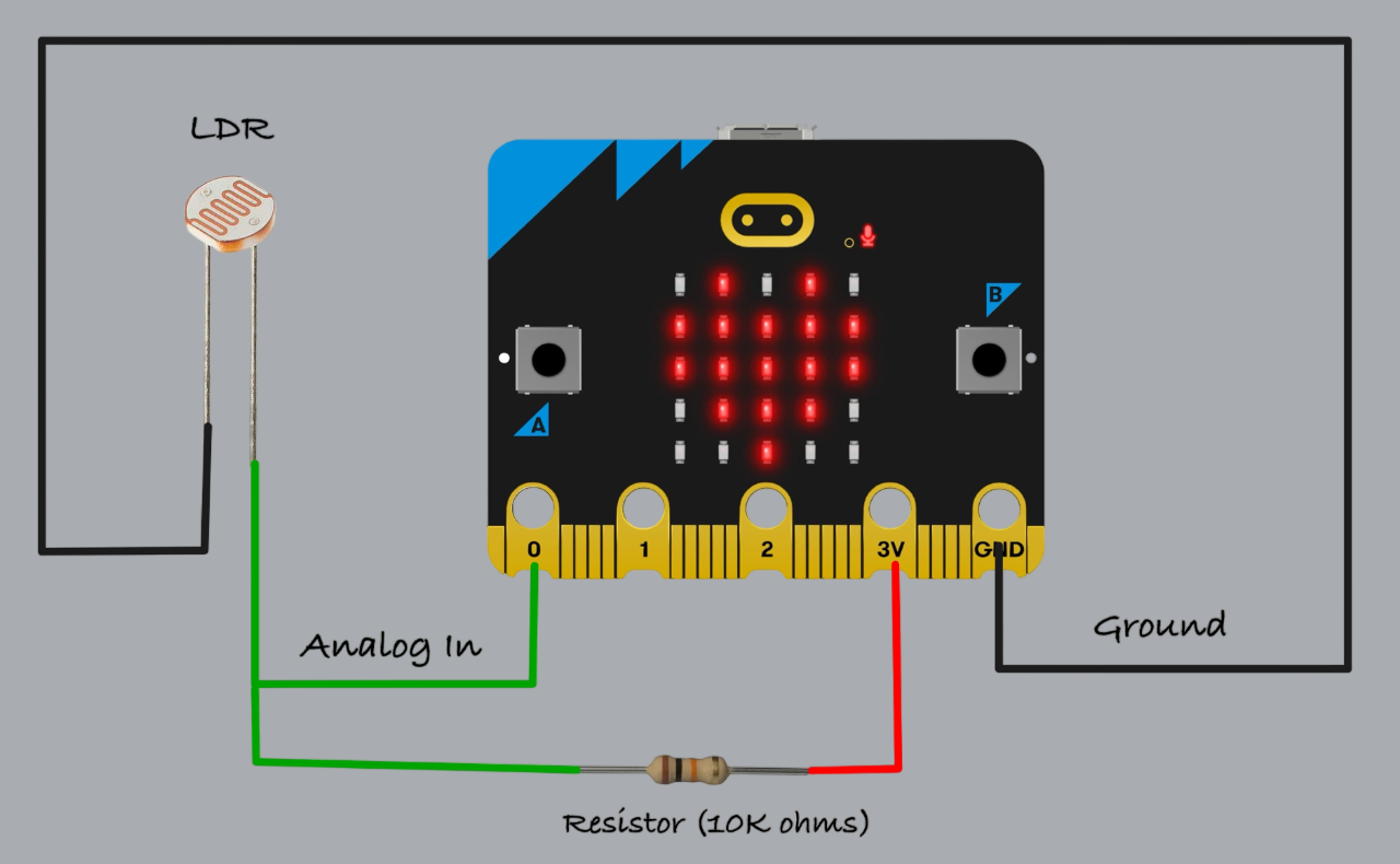
Example Circuit
Here’s a photo of the circuit I built using an LDR, alligator clips, male-to-male jumper wires, and a breadboard.
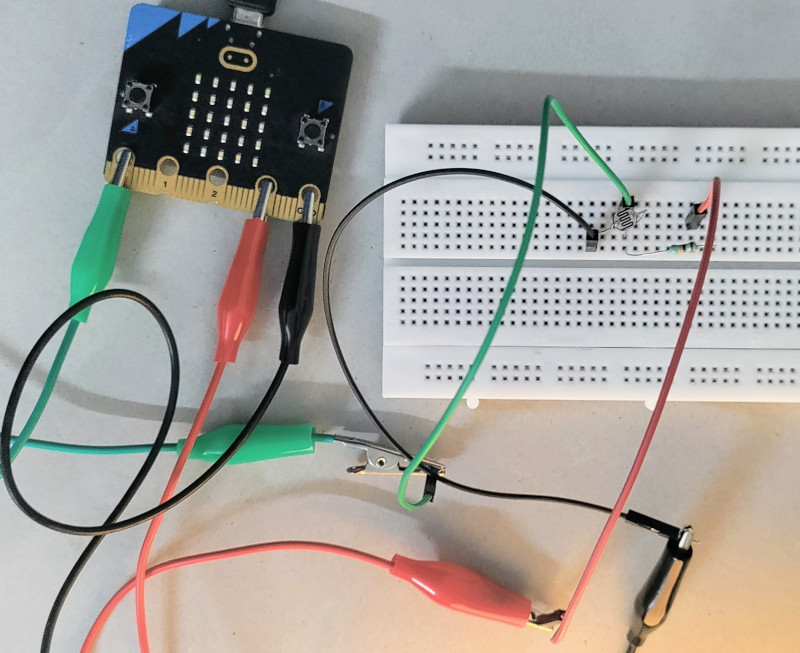
In the dark
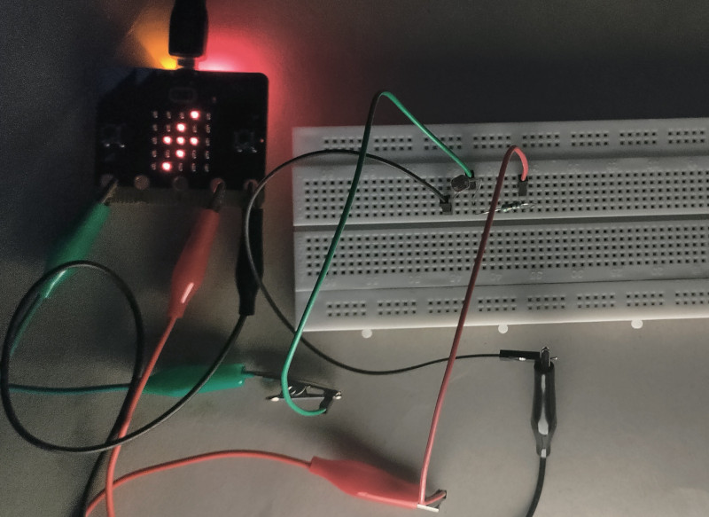
Build a Light-Activated LED Circuit with Microbit and Rust
Let's get started. We did enough theory in the last couple of sections. Time to do some coding. We'll define a threshold for the ADC value. If it goes above that (which should happen when the room gets dark), we'll show the voltage emoji (⚡) on the LED matrix.
Create Project from template
For this project, we will be using microbit-bsp (with Embassy). To generate a new project using the template, run the following command:
cargo generate --git https://github.com/ImplFerris/mb2-template.git --rev 3d07b56
-
When it prompts for a project name, type something like "led-dracula".
-
When it prompts whether to use async, select "true".
-
When it prompts you to select between "BSP" or "HAL", select the option "BSP".
Initialize Display
We will begin by initializing the micro:bit display. Then, we define a 5x5 flash emoji pattern and set the display brightness to maximum.
#![allow(unused)]
fn main() {
let board = Microbit::default();
let mut display = board.display;

#[rustfmt::skip]
const FLASH: [u8; 5] = [
    0b00010,
    0b00100,
    0b01110,
    0b00100,
    0b01000,
];
display.set_brightness(Brightness::MAX);
}
Configure ADC
We will once again use the bind_interrupts! macro to connect the SAADC interrupt to its corresponding handler.
#![allow(unused)]
fn main() {
bind_interrupts!(struct Irqs {
    SAADC => saadc::InterruptHandler;
});
}
Now let's set up the ADC. We'll configure it in single-ended mode, which means it will measure voltage on single pin relative to ground. In this case, we're using pin P0 on the micro:bit, which corresponds to GPIO pin P0.02 on the nRF52833 chip.
#![allow(unused)]
fn main() {
let channel_config = ChannelConfig::single_ended(board.p0);
let config = saadc::Config::default();
let mut adc = Saadc::new(board.saadc, Irqs, config, [channel_config]);
}
Reading Sample
Now let's read the ADC value. We'll do this in a loop and compare the result against a threshold. The sample function requires a mutable buffer with the same number of elements as the number of channels we configured. Since we’re only using one channel, we provide a 1-element array. The ADC will perform the conversion and store the result in the first (and only) element of the array.
#![allow(unused)]
fn main() {
let mut buf = [0; 1];
adc.sample(&mut buf).await;
}
Displaying Emoji
Once we have the ADC value, controlling the LED display is straightforward. If the value is greater than a certain threshold (in this case, 3500), we show the emoji. Otherwise, we clear the display. You can tweak the threshold to make it more or less sensitive depending on your setup.
#![allow(unused)]
fn main() {
const THRESHOLD: i16 = 3500;
}
#![allow(unused)]
fn main() {
if buf[0] > THRESHOLD {
    display.apply(display::fonts::frame_5x5(&FLASH));
    display.render();
} else {
    display.clear();
}
```rust

}
Final code
#![no_std]
#![no_main]

use embassy_executor::Spawner;
use embassy_nrf::{
    bind_interrupts,
    saadc::{self, ChannelConfig, Saadc},
};
use microbit_bsp::{
    Microbit,
    display::{self, Brightness},
};

use {defmt_rtt as _, panic_probe as _};

bind_interrupts!(struct Irqs {
    SAADC => saadc::InterruptHandler;
});

const THRESHOLD: i16 = 3500;

#[embassy_executor::main]
async fn main(_spawner: Spawner) -> ! {
    let board = Microbit::default();
    let mut display = board.display;

    let config = saadc::Config::default();
    let channel_config = ChannelConfig::single_ended(board.p0);
    let mut adc = Saadc::new(board.saadc, Irqs, config, [channel_config]);

    #[rustfmt::skip]
    const FLASH: [u8; 5] = [
        0b00010,
        0b00100,
        0b01110,
        0b00100,
        0b01000,
    ];

    display.set_brightness(Brightness::MAX);
    loop {
        let mut buf = [0; 1];
        adc.sample(&mut buf).await;
        if buf[0] > THRESHOLD {
            display.apply(display::fonts::frame_5x5(&FLASH));
            display.render();
        } else {
            display.clear();
        }
    }
}
Clone the existing project
You can also clone (or refer) project I created and navigate to the ldr-dracula folder.
git clone https://github.com/ImplFerris/microbit-projects
cd microbit-projects/bsp-embassy/ldr-dracula
Flash
All that's left is to flash the code to your micro:bit and see it in action.
Run the following command from your project folder:
#![allow(unused)]
fn main() {
cargo run
}
Now try turning off the room light, moving the LDR to a darker area, or simply covering it with your hand. You should see the LED matrix display the voltage emoji when it gets dark enough. If it doesn't trigger as expected, you can adjust the threshold value to better match your environment.